
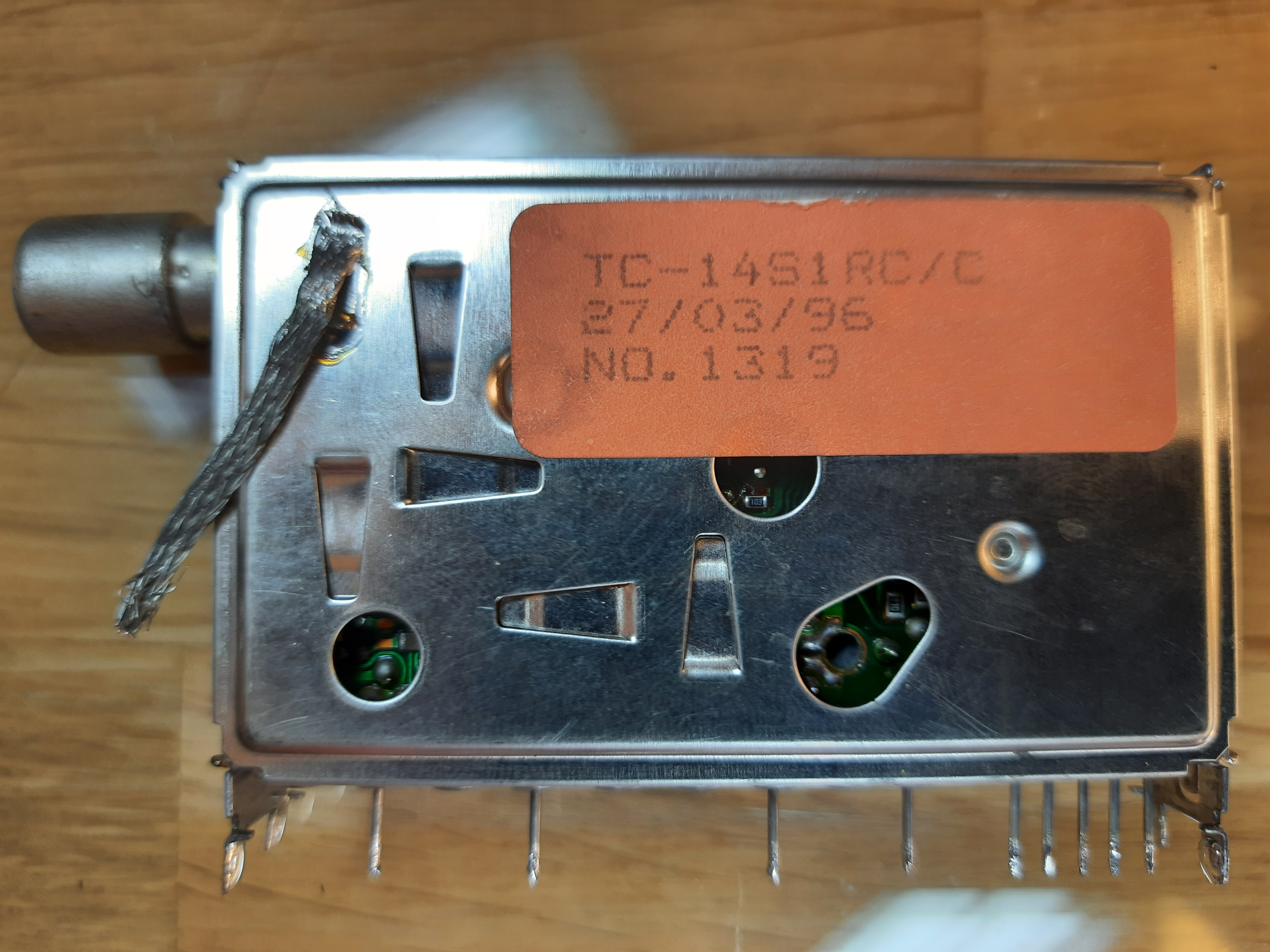
TV Tuner
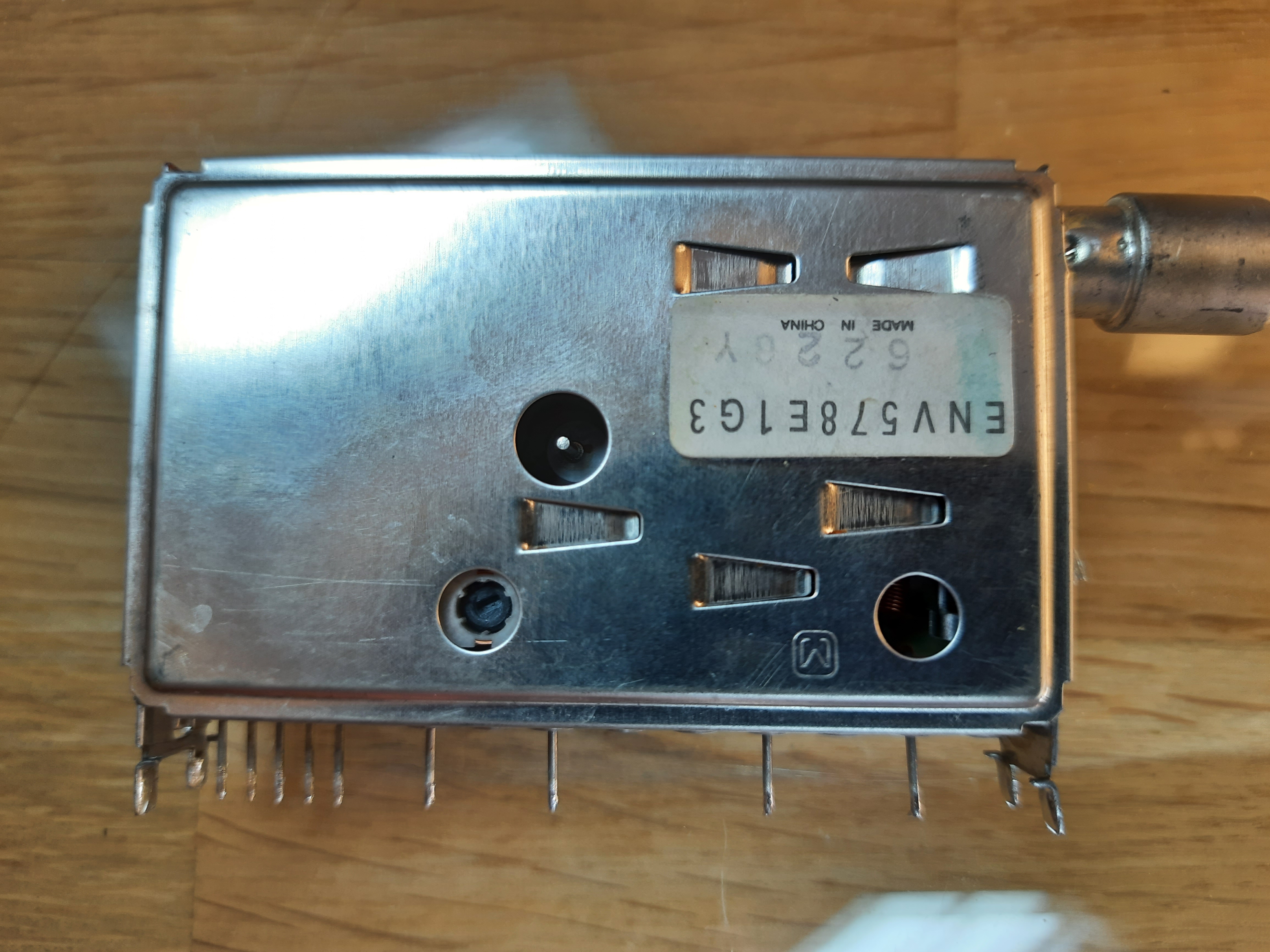
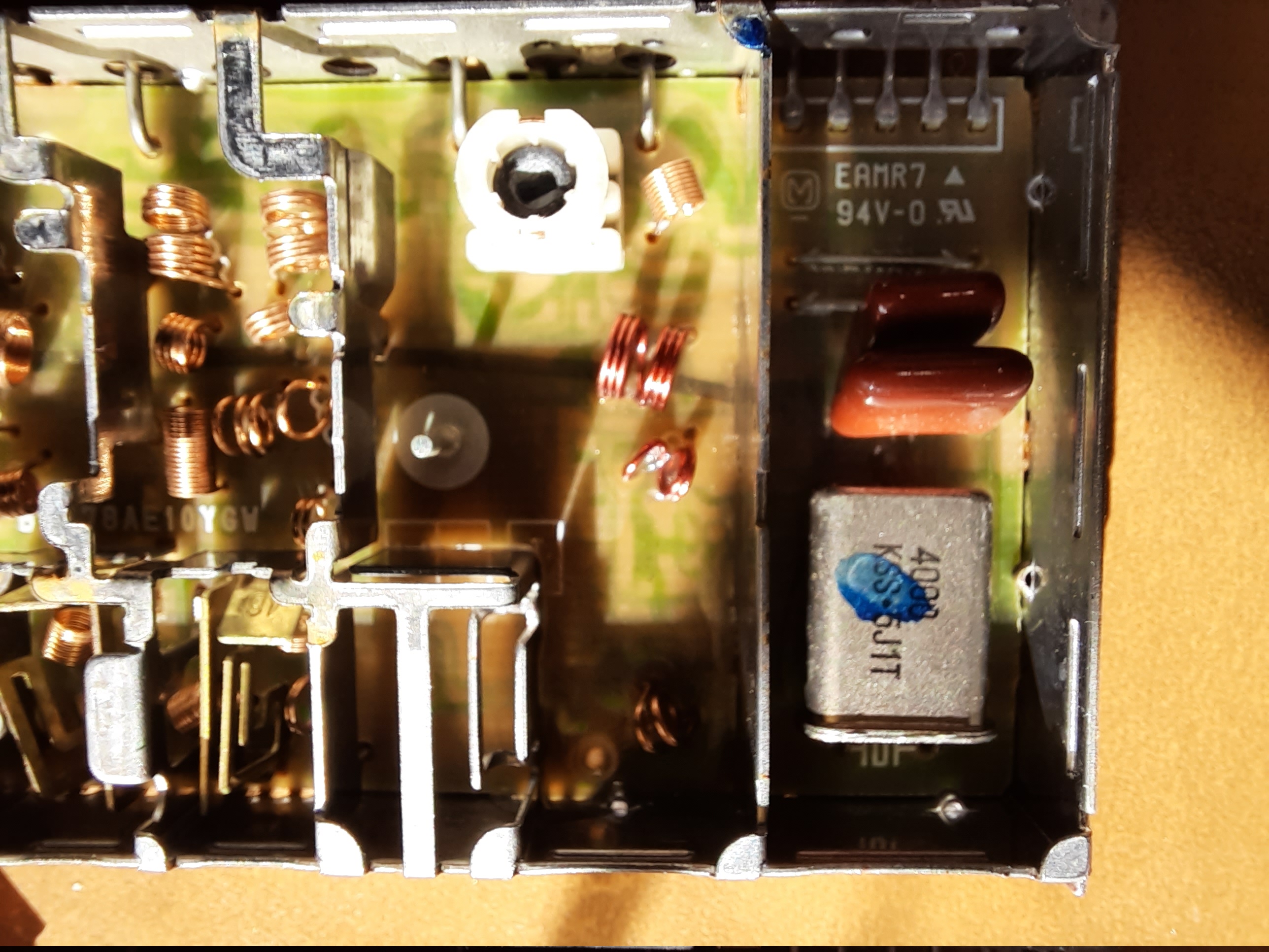
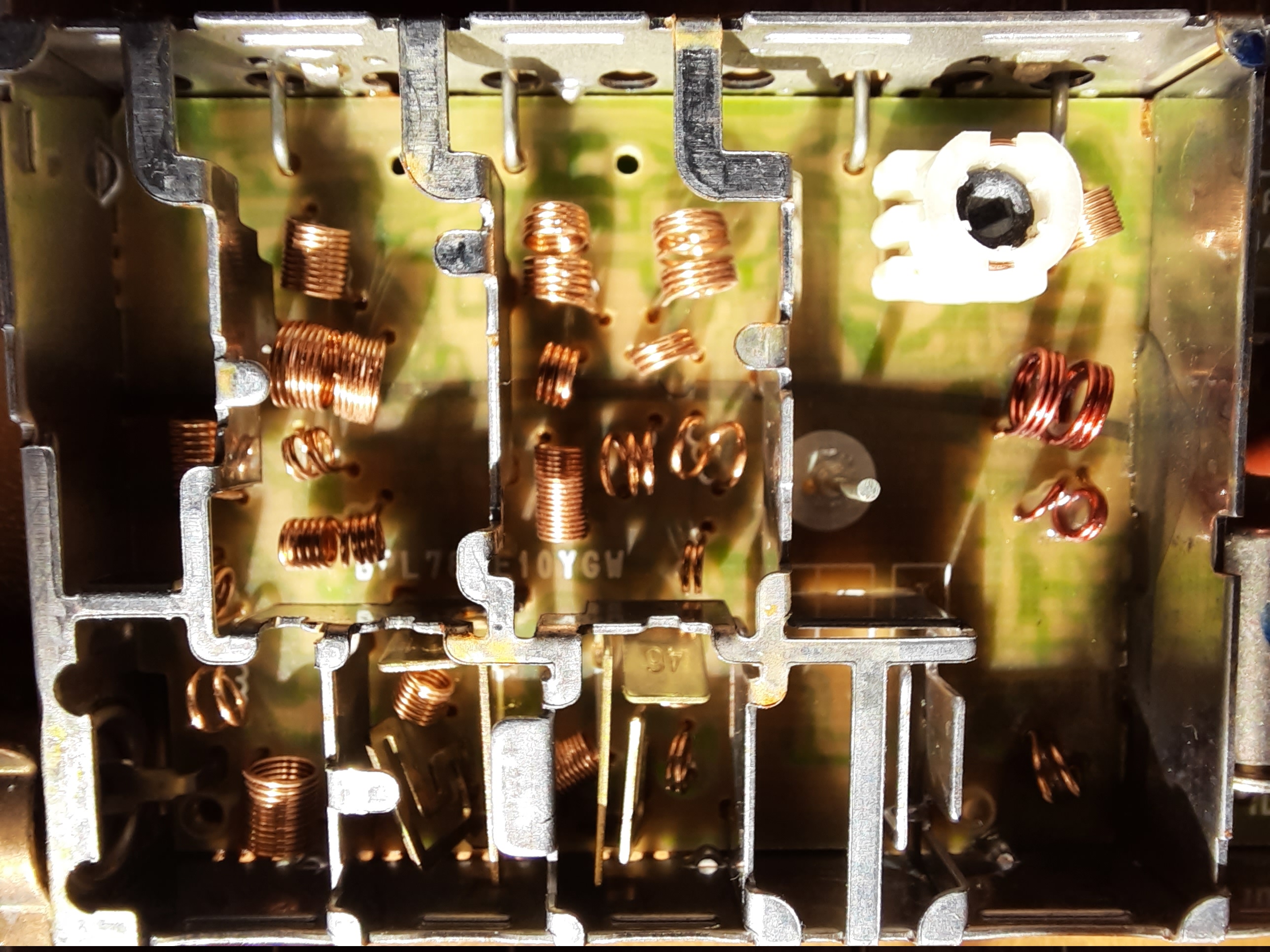
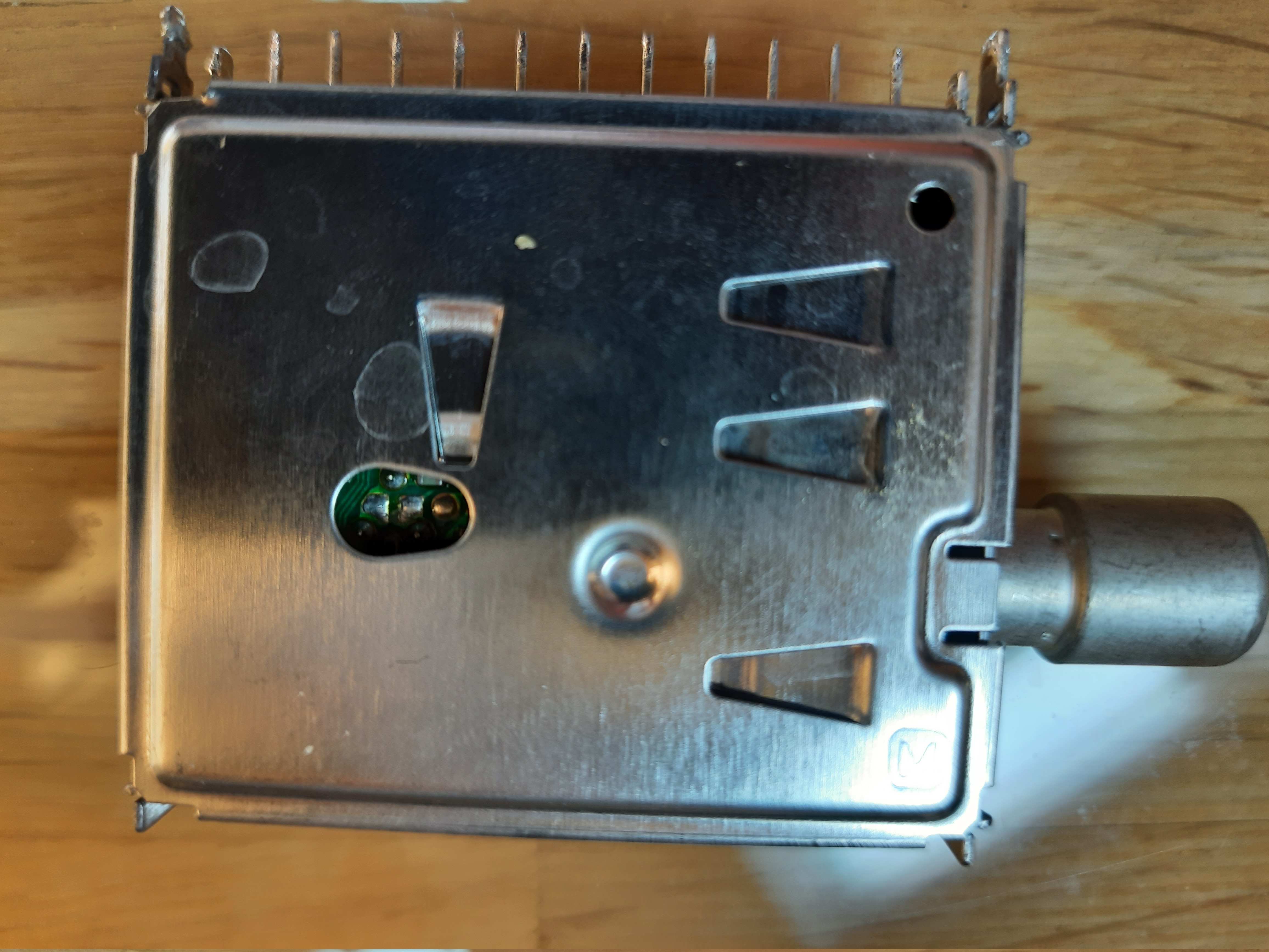
Tuner ENV578E1G3
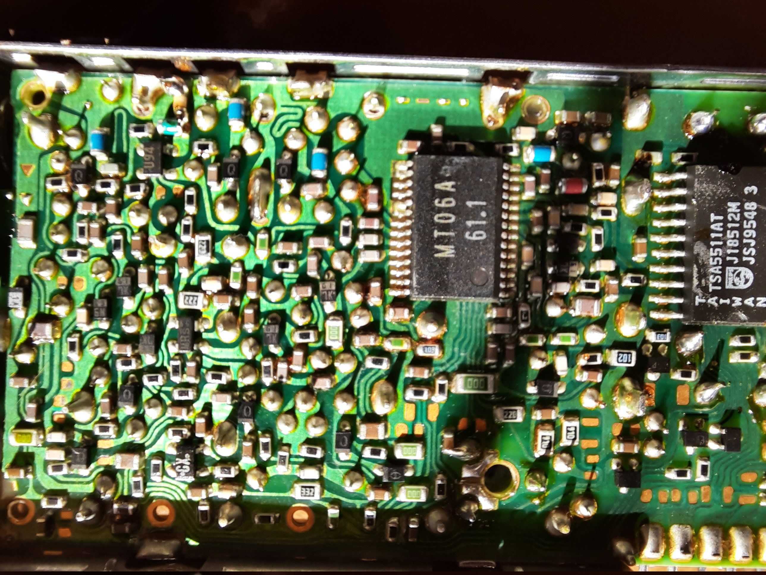
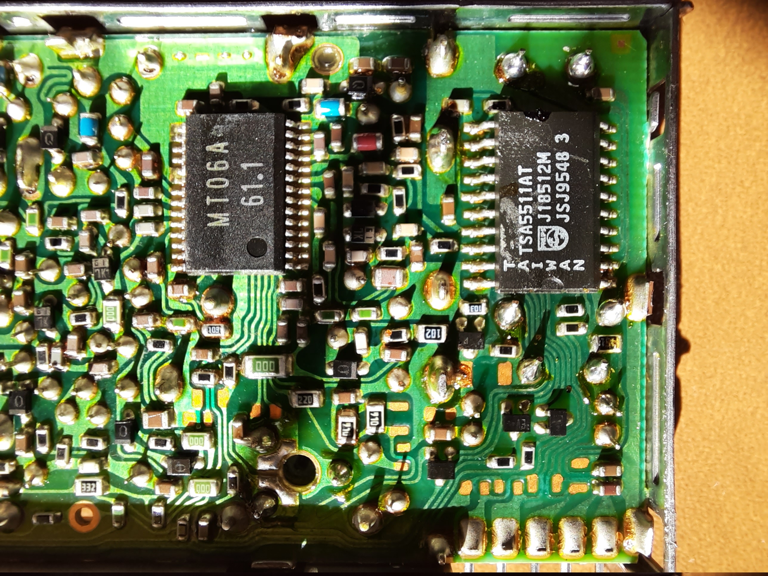
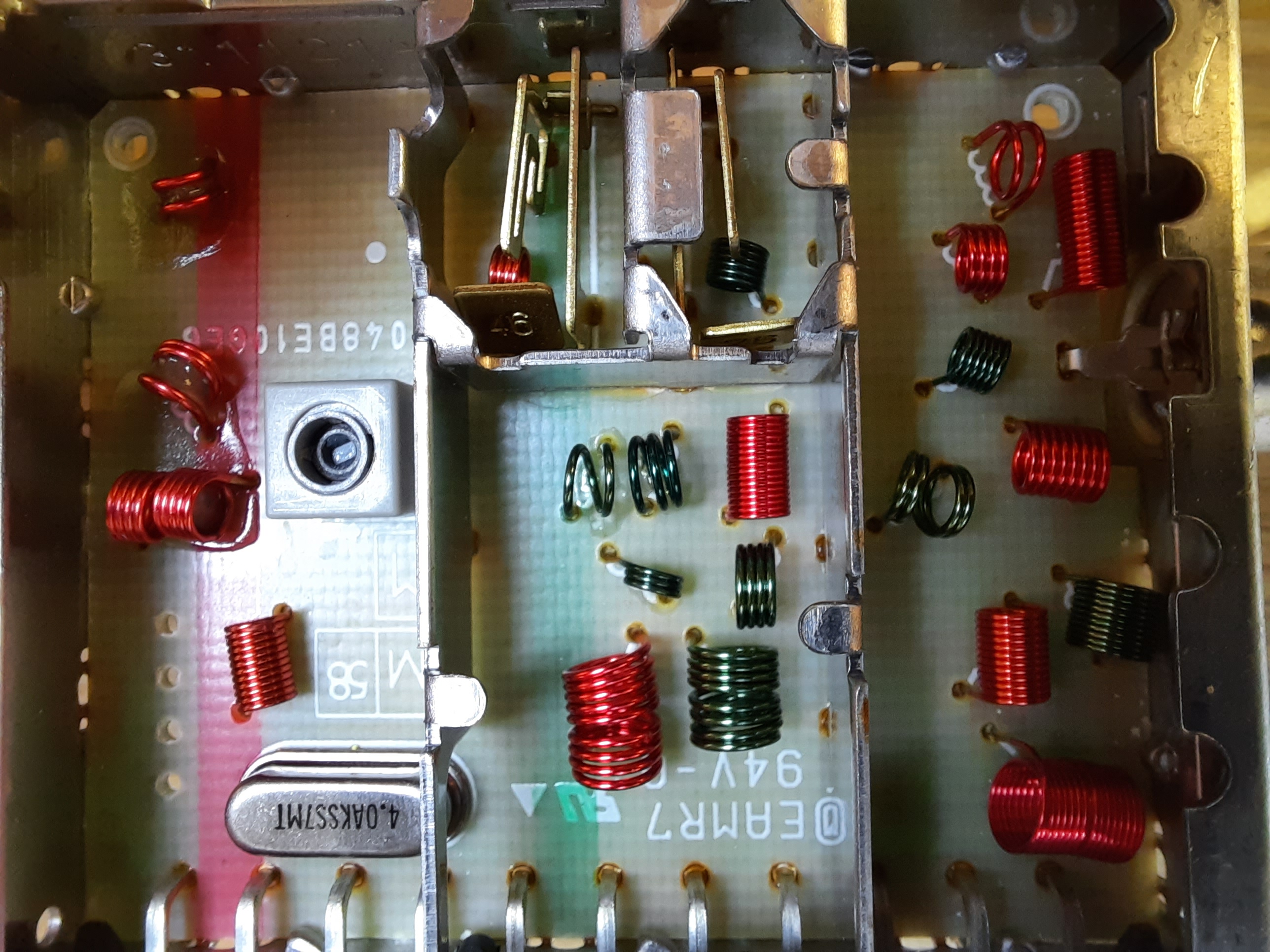
Tuner from 1996. Main chips are TSA5511AT and MT06A.
While TSA5511 is the PLL Synthesizer, which generates all required frequencies, the MT06A is unknown to me. But it must be the RF mixer, which produces the IF output by mixing input signal with PLL synthesizer output.
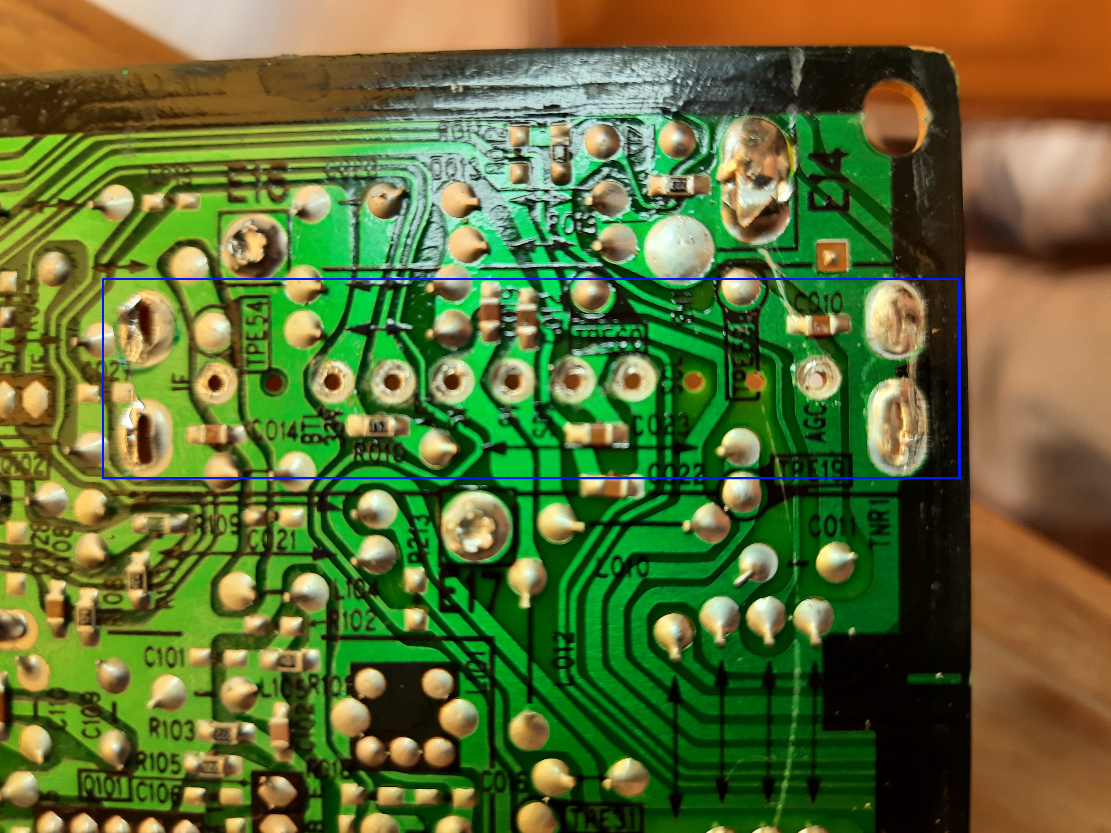
Connector has 5 small pins and 4 large pins. In my listing, numbering starts with outermost small pin. To check against reality, compare against my image from the original TV board.
| Pin | Meaning | Comment |
|---|---|---|
| 1 | 30V | Needed to generate control voltage for VARIAC |
| 2 | 5V | |
| 3 | SCL | |
| 4 | SCA | |
| 5 | AD | Address Select? |
| 6 | IF | IF output |
| 7 | BM | ? |
| 8 | AGC | |
| 9 | BT | ? |
 XTAL should be a 4 Mhz type.
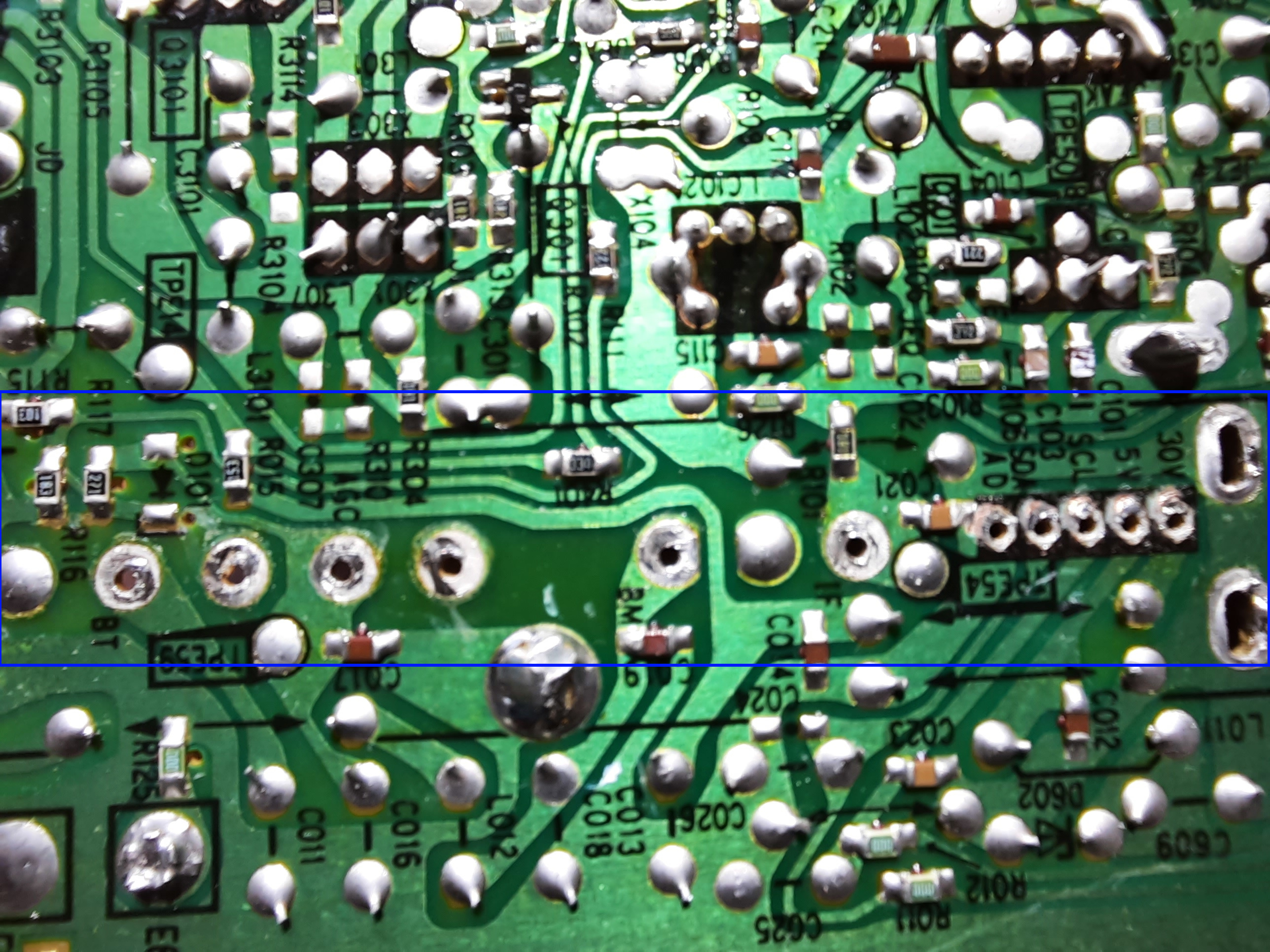
TV board where tuner was taken from (a Panasonic TV)
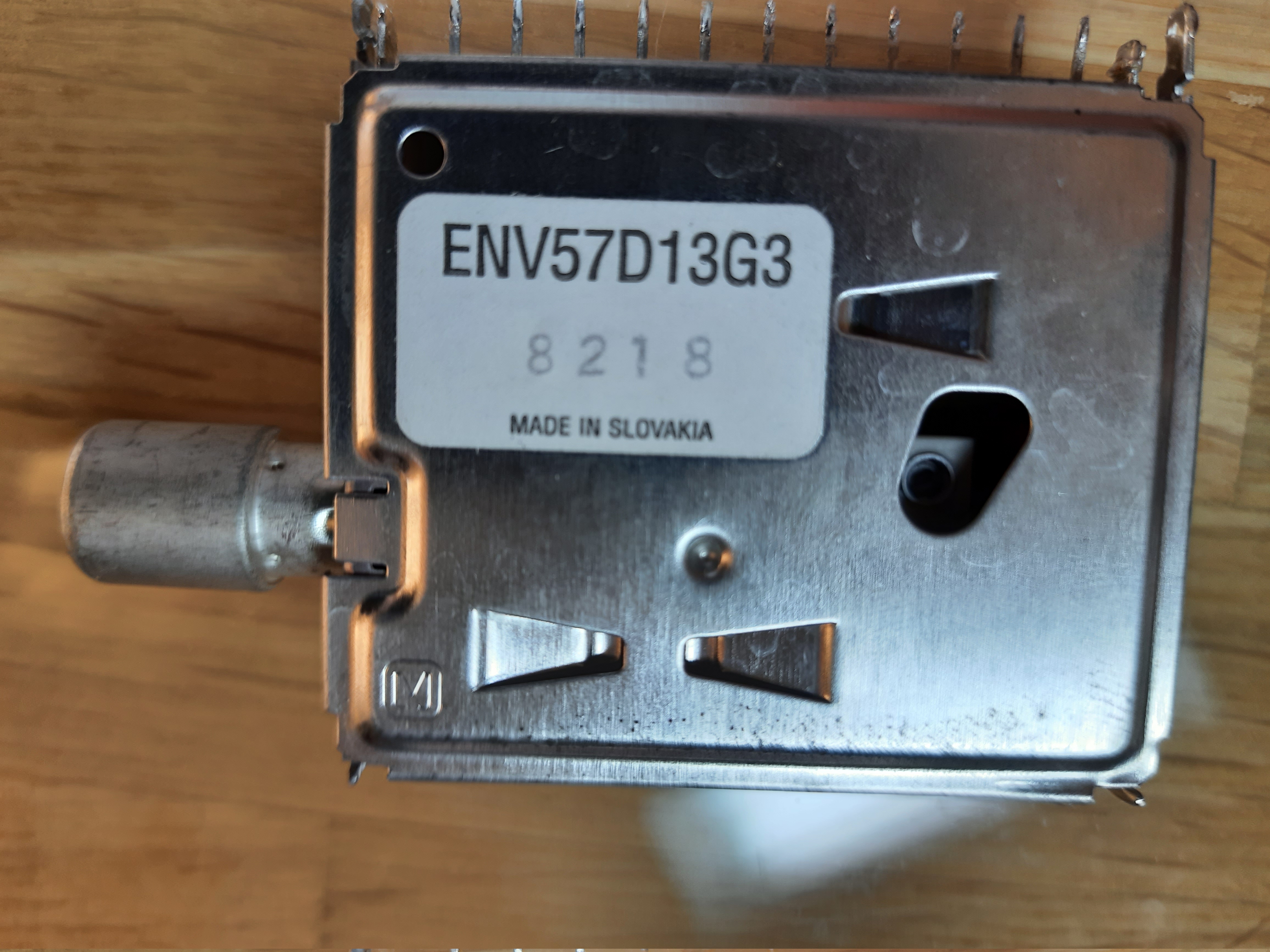
Tuner ENV57D13G3
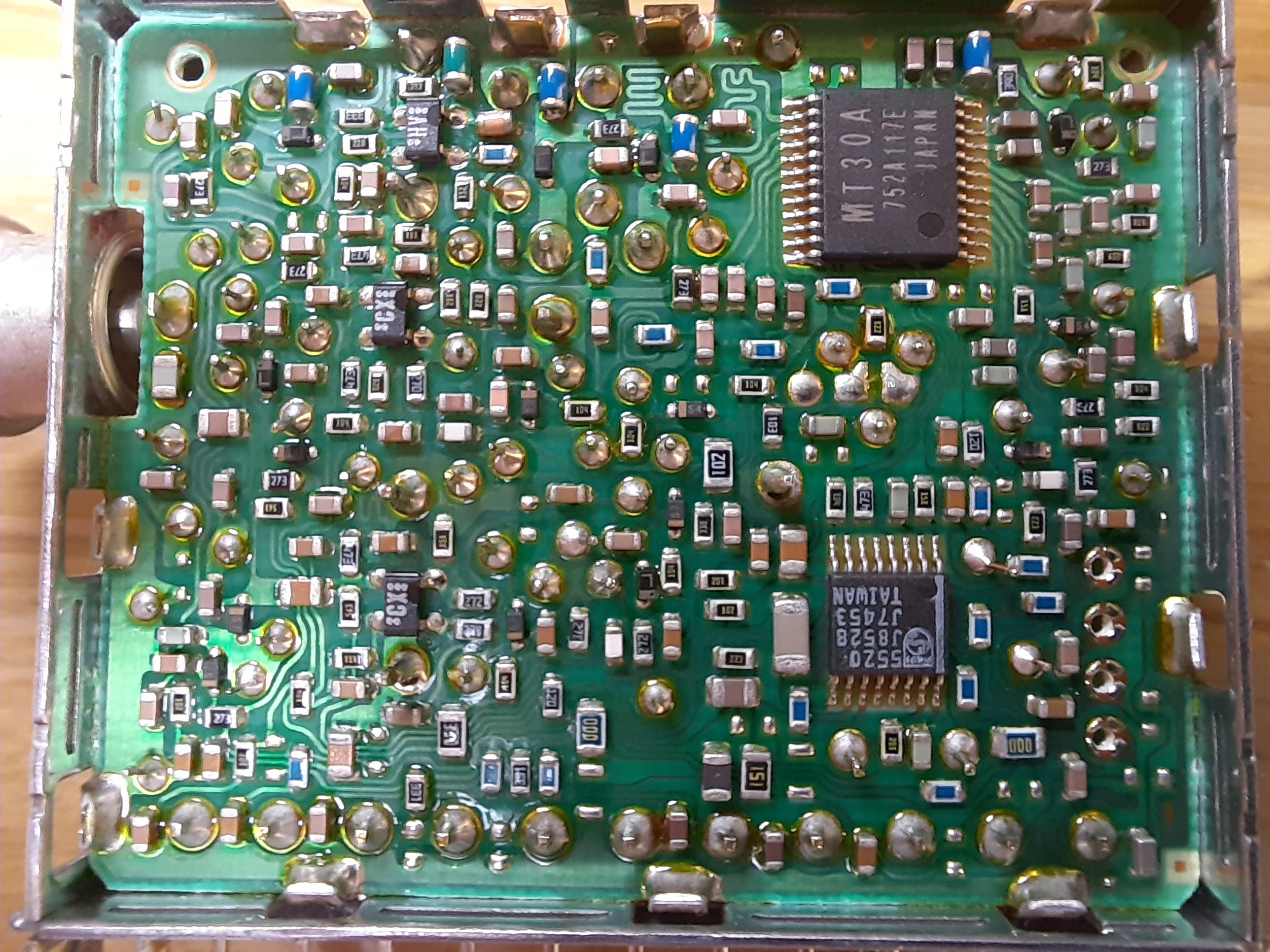
My second tuner was also taken from another Panasonic TV. It is smaller and obviously more modern than the one above.
Main chips are TSA5520 and MT30A. 11 Pins.
In my numbering below, Pin 1 starts with pin closest to RF input. To check against reality, compare against my image from the original TV board.
| Pin | Meaning | Comment |
|---|---|---|
| 1 | AGC | |
| 2 | ? | Was not connected on TV board |
| 3 | ? | Was not connected on TV board |
| 4 | SCL | |
| 5 | SDA | |
| 6 | 9V | |
| 7 | 5V | |
| 8 | 33V | or AFC? |
| 9 | BTL | or 33V? |
| 10 | ? | Was not connected on TV board |
| 11 | IF | IF output |
 XTAL is a 4 Mhz type.
TV board where tuner was taken from (a Panasonic TV)
References
http://www.rfcandy.biz/communication/supertuner.html
https://www.qsl.net/sv1bkg/super_scanner/
https://mekweb.eu/?lang=en&q=download-details&file=83 with some info on pin meanings for these tuner modules