
Experimenting with an old FM tuner
I tried to buy a variable capacitor via ebay. What I got was the variable capacitor together with a small metal box. The box contains a FM tuner. It contains two germanium transistors AF121/AF125 and it seems it is from the 1960ies.
 (click to view larger version)
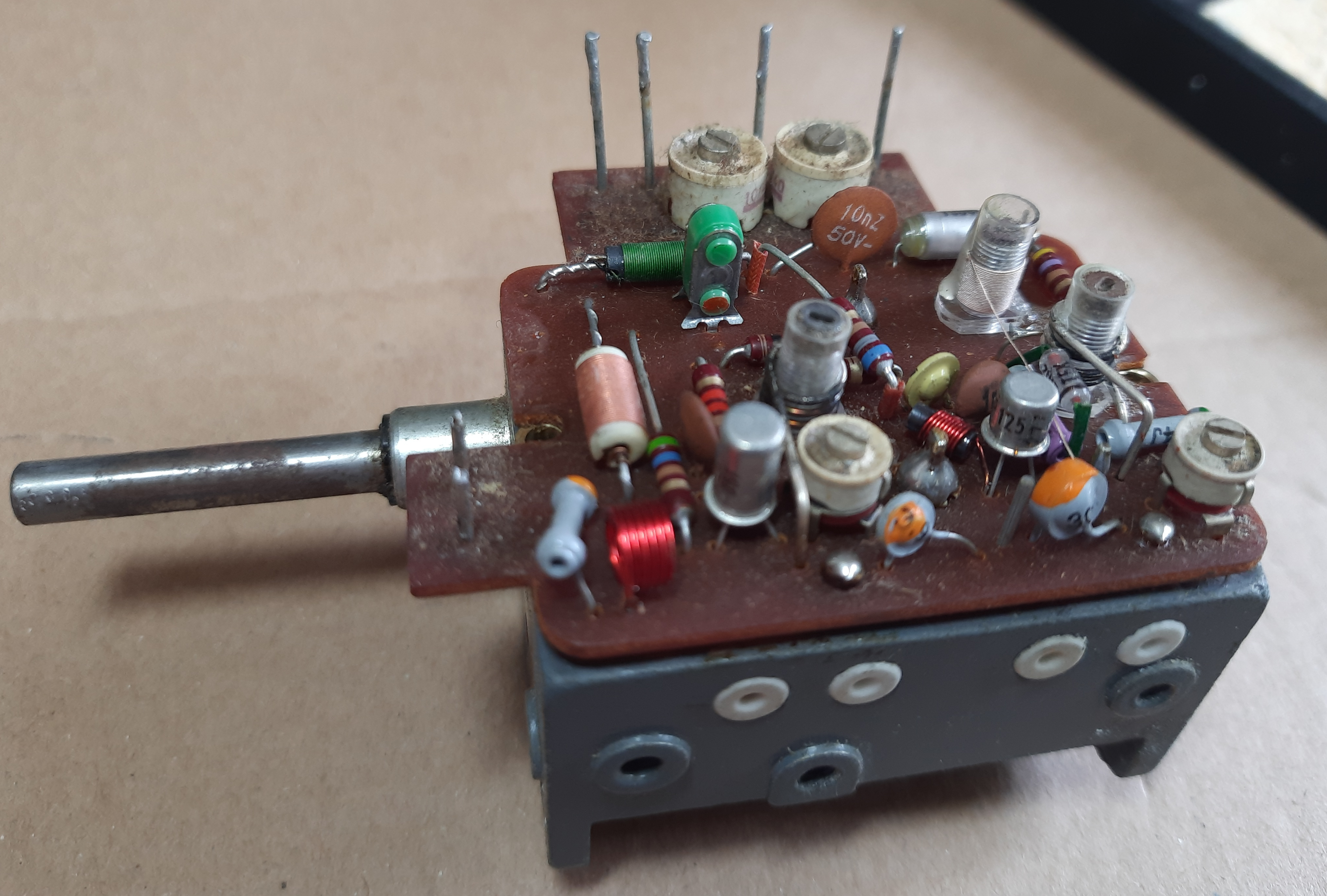
This picture shows the variable capacitor, forming the base for the FM tuner. Metal box has been removed.
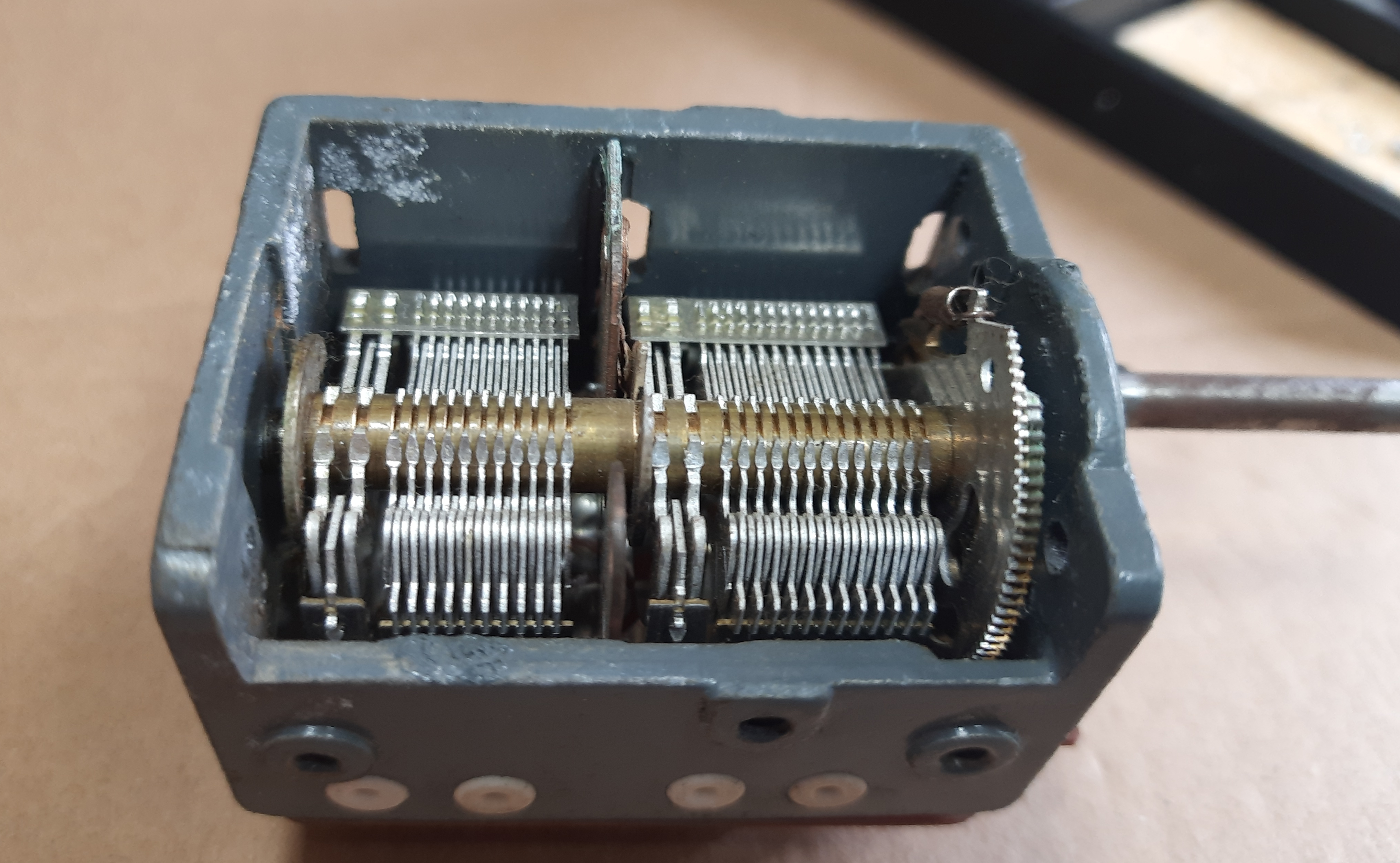
I was not able to move the shaft/axis of the capacitor. This needed to be fixed first.
 (click to view larger version)
View on capacitor
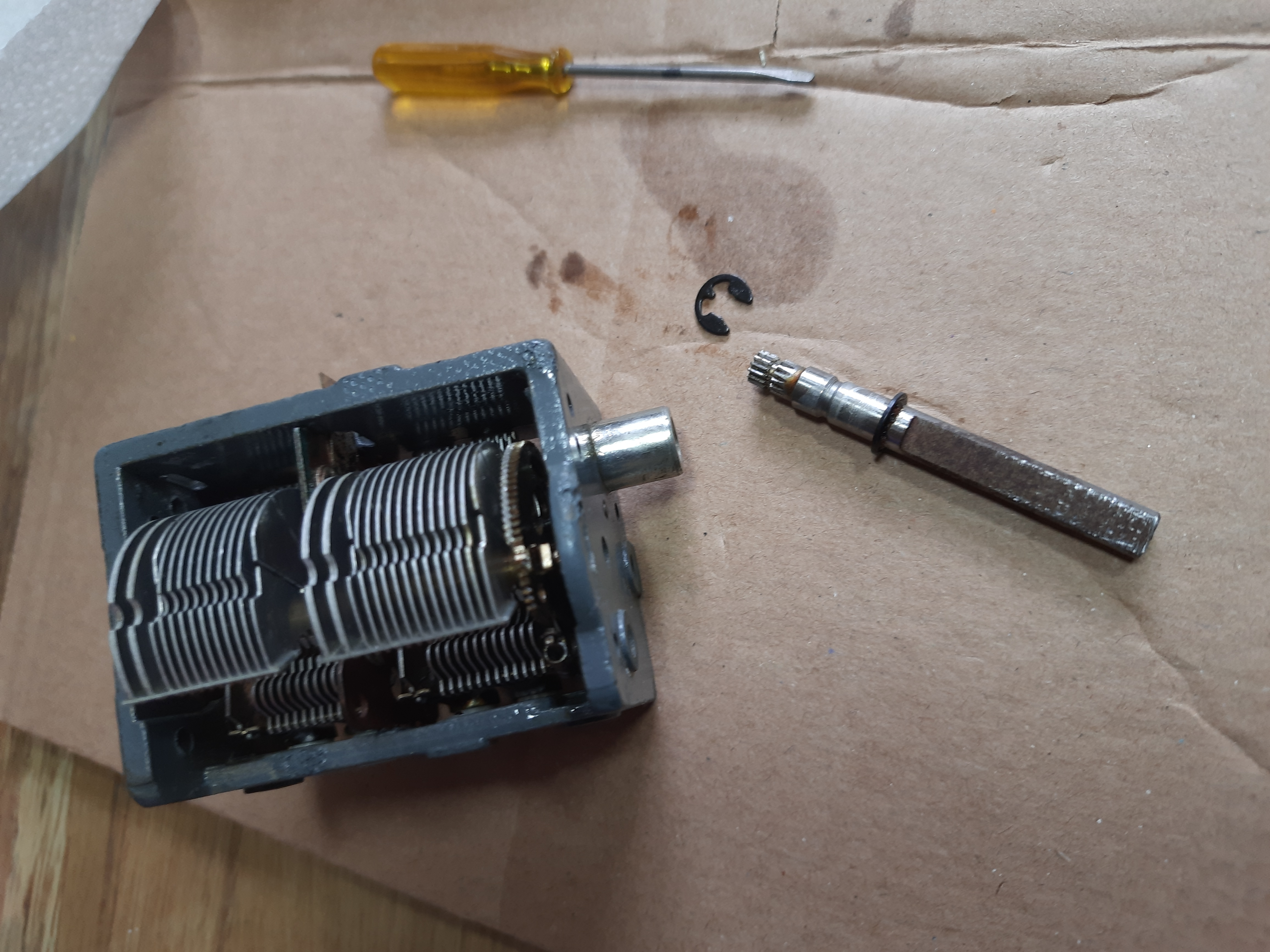
The shaft of the capacitor can simply be removed.
 (click to view larger version)
Removed shaft.
I’ve pulled out rusty shaft, also with hardened oil at the and replaced it with new oil. After that and some cleaning, the capacitor could be moved like new.
Next was to measure capacitance. I used my DIY Capmeter – Kapazitätsmessgerät mit dem AVR . For very low values like some pF, it is not 100% precise.
 (click to view larger version)
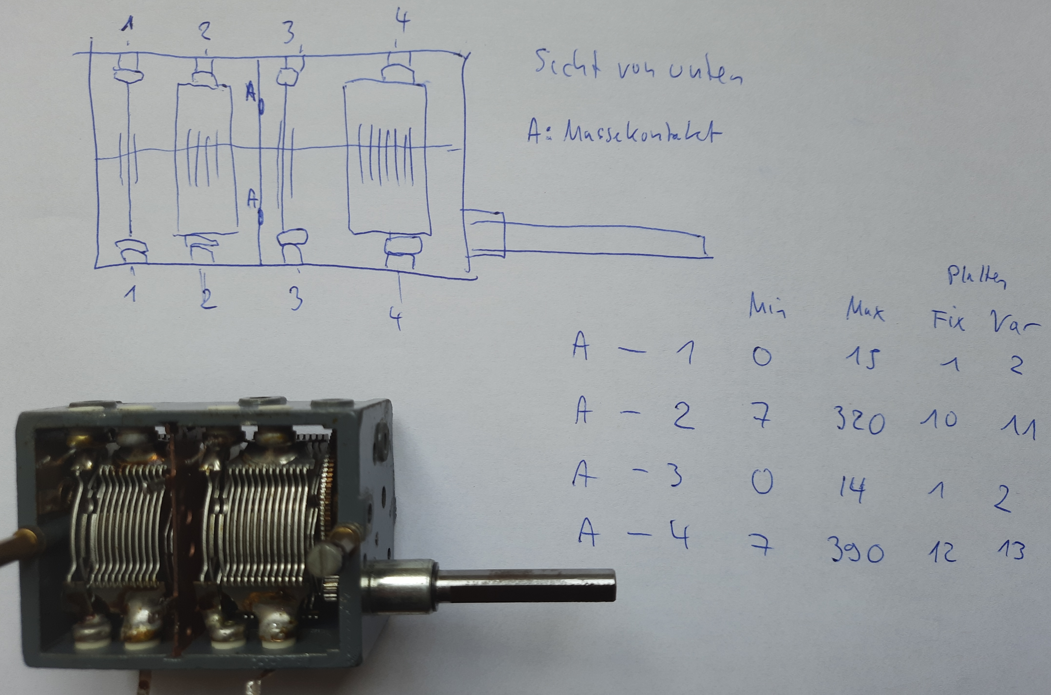
The capacitor is in fact a 4 x capacitor with a common shaft. Two of them are about 0-15 pF, one about 7-320 pF, one has about 7-390 pF. See my table. I also counted the number of fixed/variable plates which is 1/2 for the 15 pF capacitors, 10/11 for the 320 pF and 12/13 for the 390 pF capacitor. one end of the capacitors is connected to common ground (‘A’ in my hand drawn picture).
 (click to view larger version)
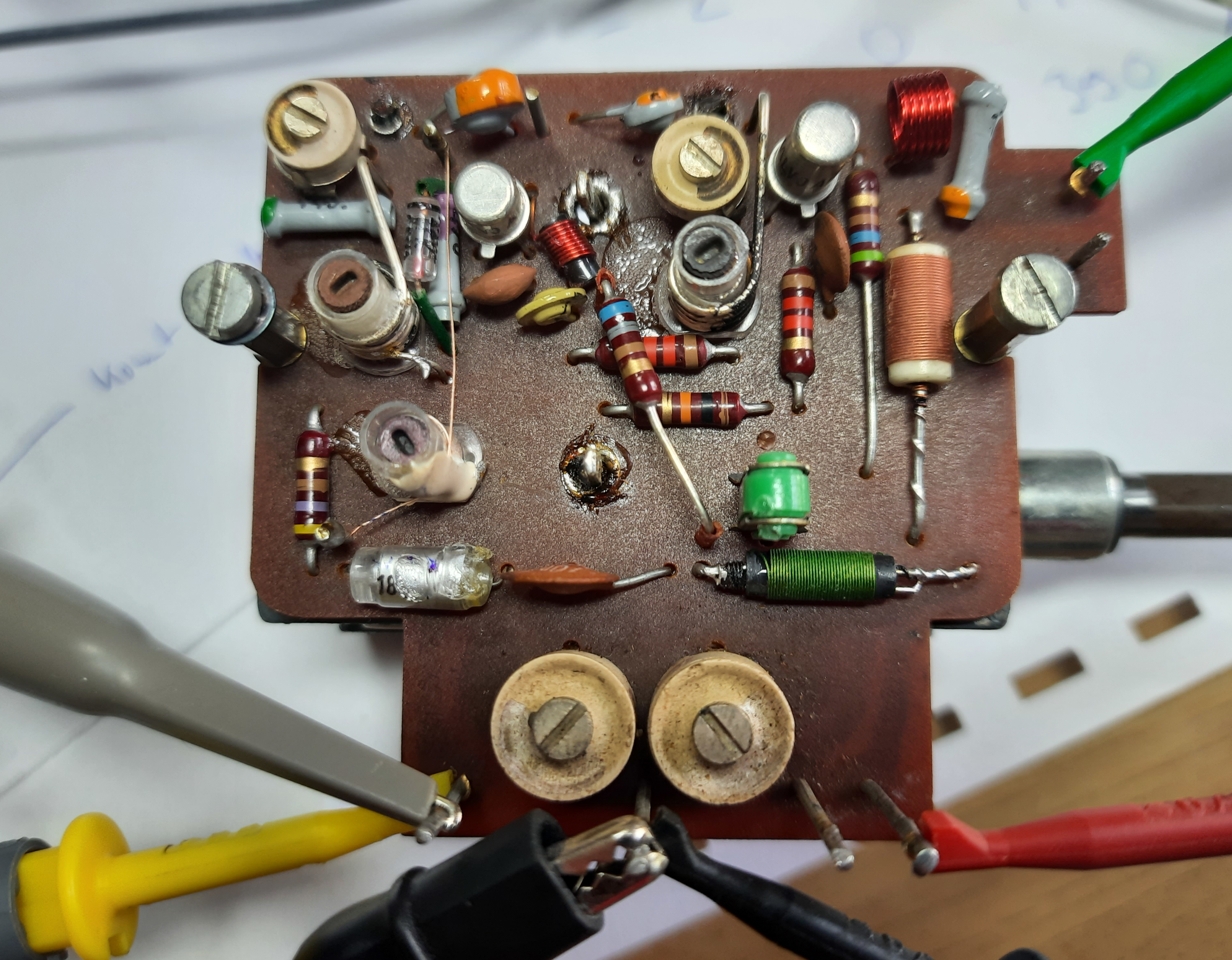
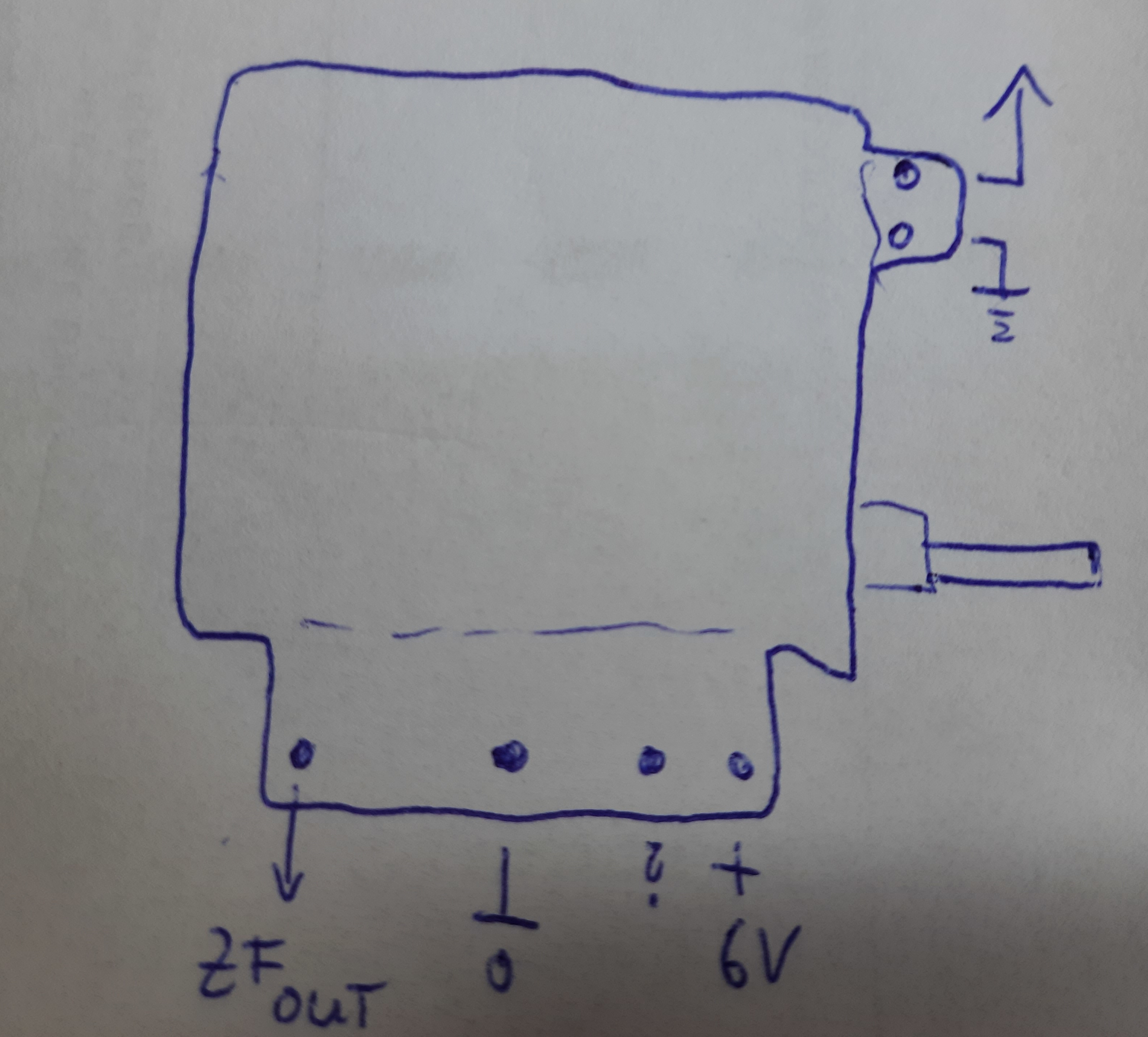
FM tuner with connections. Antenna (upper right, green cable). +6Volt (lower right, red), GND lower mid (black), IF out (lower left, yellow). If really 6V are reqired, I don’t know.
When checking the Internet for a scheme of that old tuner, I did not find that, but another guy that also has experimented with that tuner: https://elektronikbasteln.pl7.de/zeitreise-durch-die-technik-der-ukw-tuner
 (click to view larger version)
Connections of FM tuner
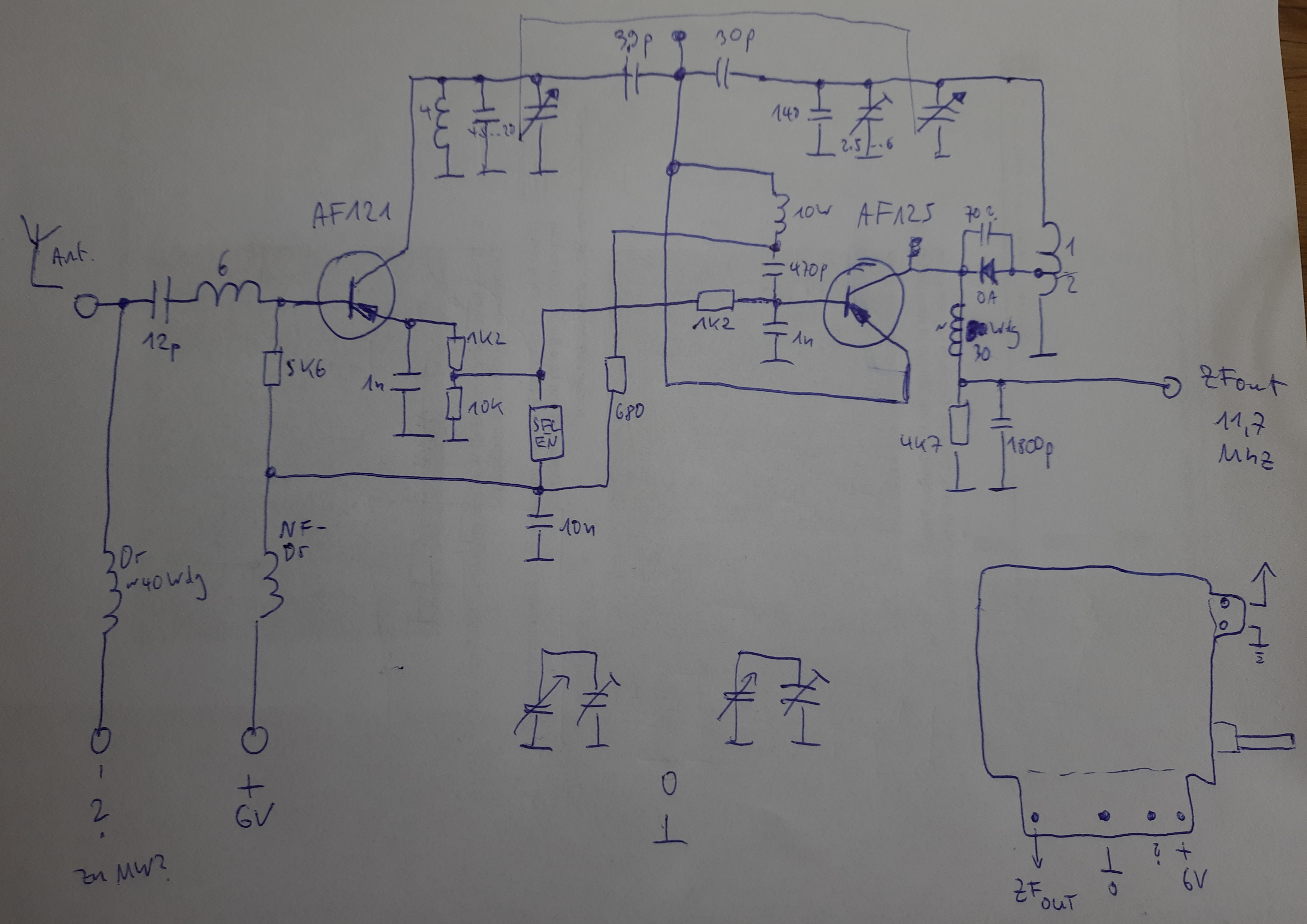
I tried to re-engineer the scheme of the tuner. result is below. Input is FM range (about 87..108 MHz). It used a AF121 in the first stage, and a AF125 in mixer stage. Output signal has IF frequency 11.7MHz.
 (click to view larger version)
The two large trimmers at the bottom of the PCB seems only be connected to the variable capacitors 320 and 390 pF section, but are not connected to the FM tuner. There is also an element called ‘SELEN’ in the scheme, it is a green component on the PCB. This seems to be a voltage controlling element, made from Selen. The diode is a germanium OA xx, where I cannot read the exact type number.
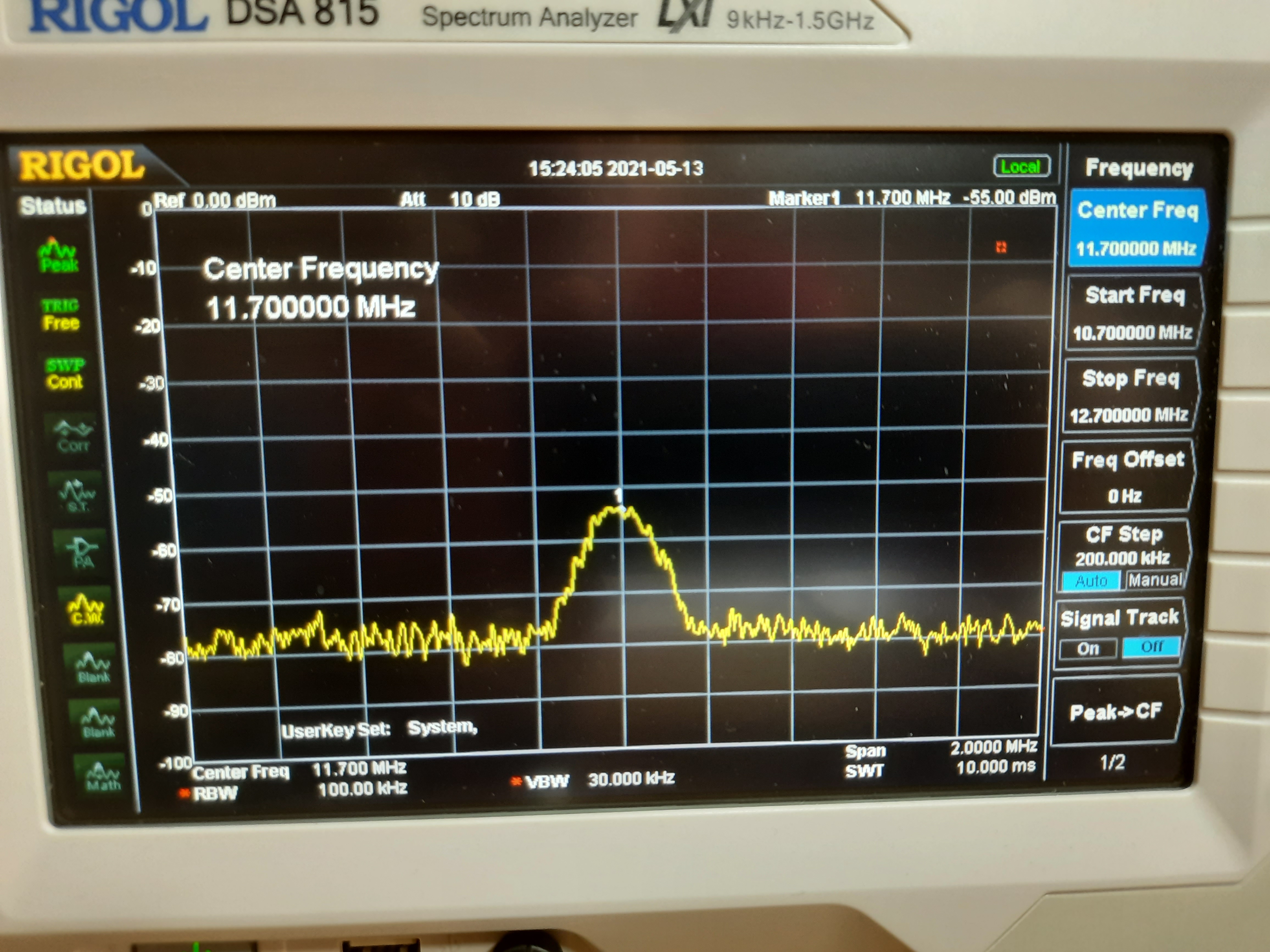
The last picture shows the FM tuner signal, hooked to a spectrum analyzer. The spectrum analyzer is able to do FM demodulation at any frequency, so I was able to hear radio stations with the analyzers headphone output.
 (click to view larger version)
Signal at 11.7Mhz, tuned onto a strong local radio station