Modulation and Demodulation - HF-Probe
When searching for a scheme for a HF probe, I found a good working solution at https://elektronikbasteln.pl7.de/signalverfolger-fuer-nf-und-hf-selbst-gebaut .
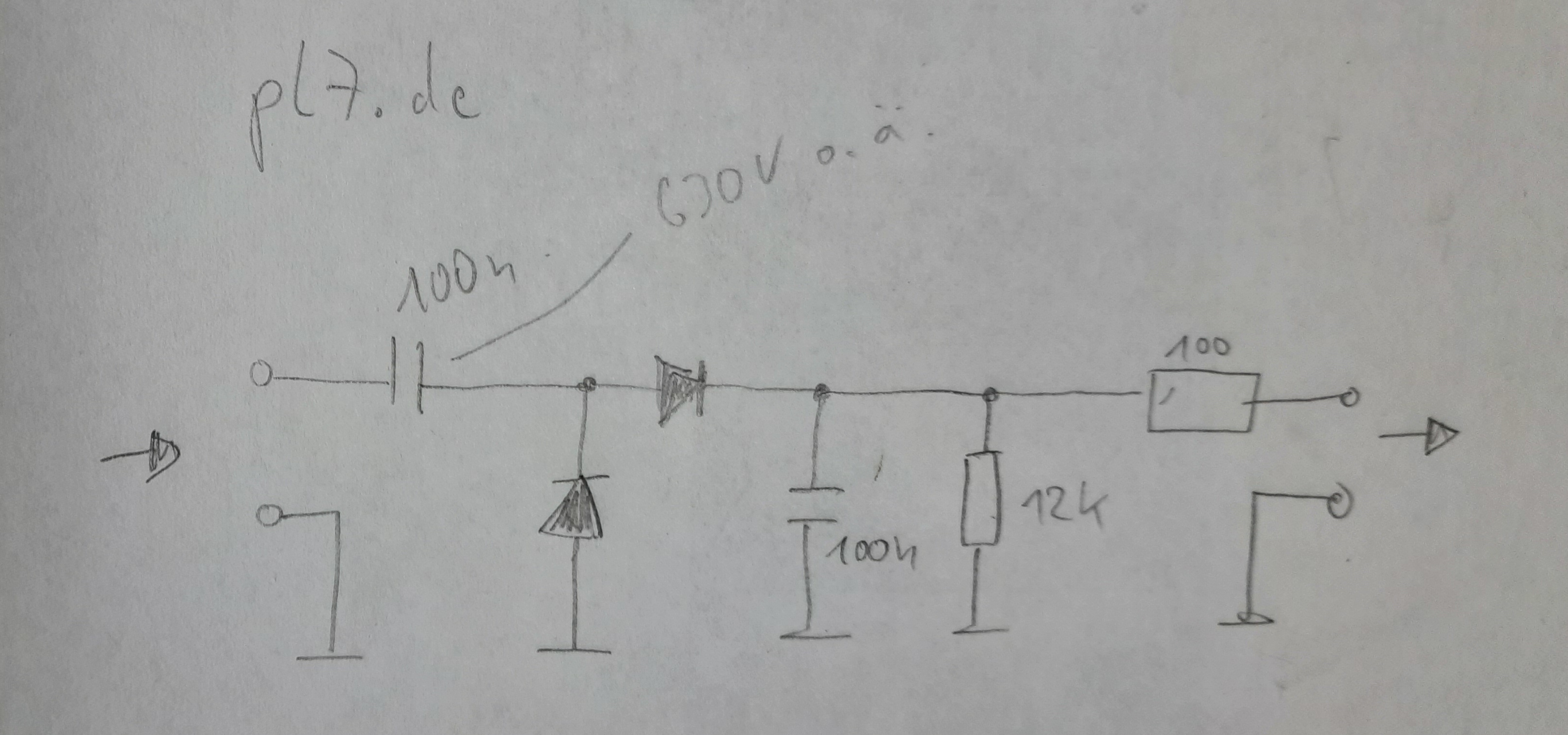
The scheme uses two germanium rectifiers and looks like this:
 (click to view larger version)
My hand drawing, a better image can be found on https://elektronikbasteln.pl7.de/signalverfolger-fuer-nf-und-hf-selbst-gebaut
I tried that HP probe schema with good results. The original uses 2 diodes AA118, I have used AA143.
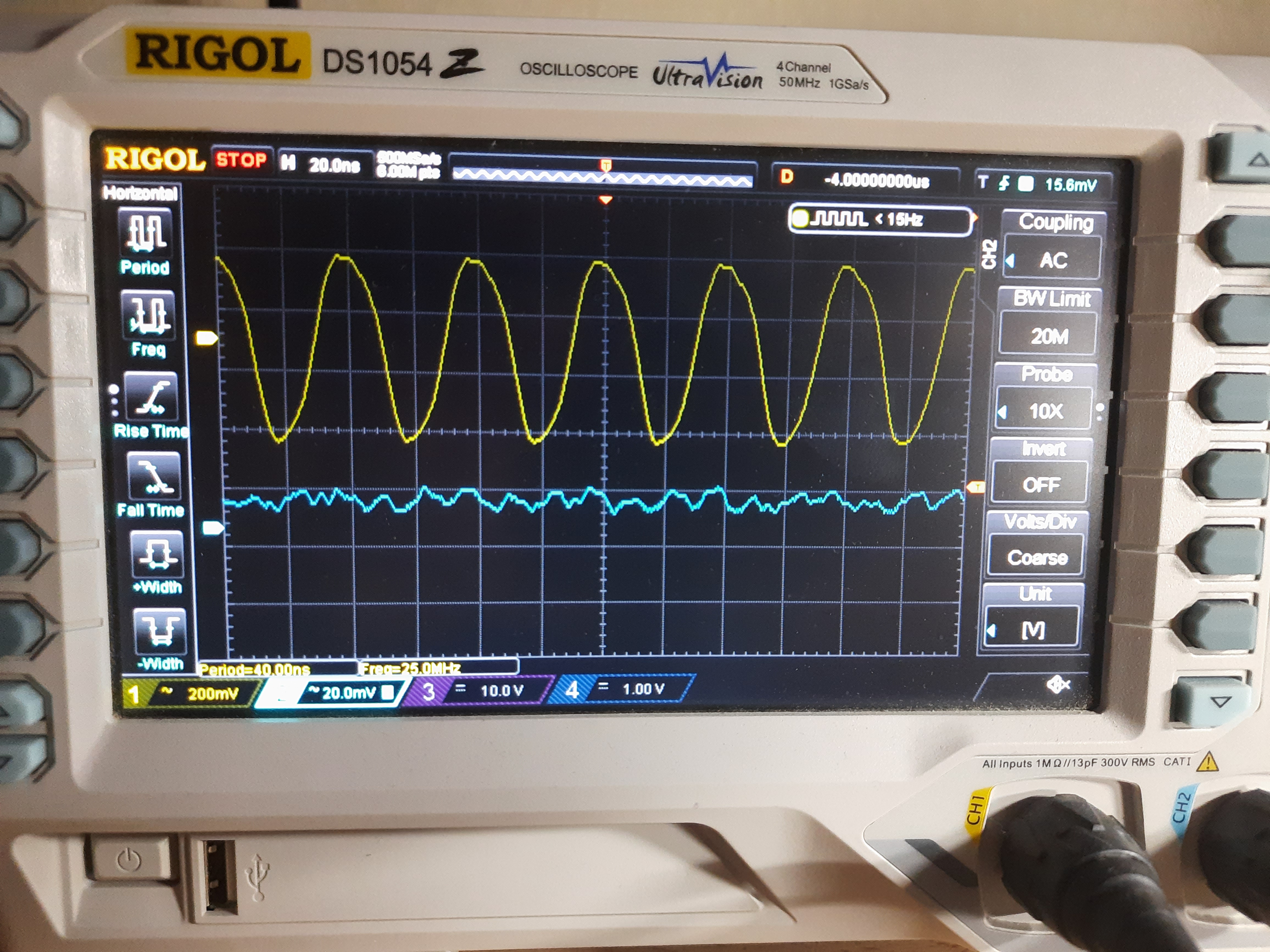
In the next images, we can see a 25 MHz signal, AM-modulated with a 1 KHz signal. This signal is generated by my frequency generator oldie WF PG1 Prüfgenerator.
 (click to view larger version)
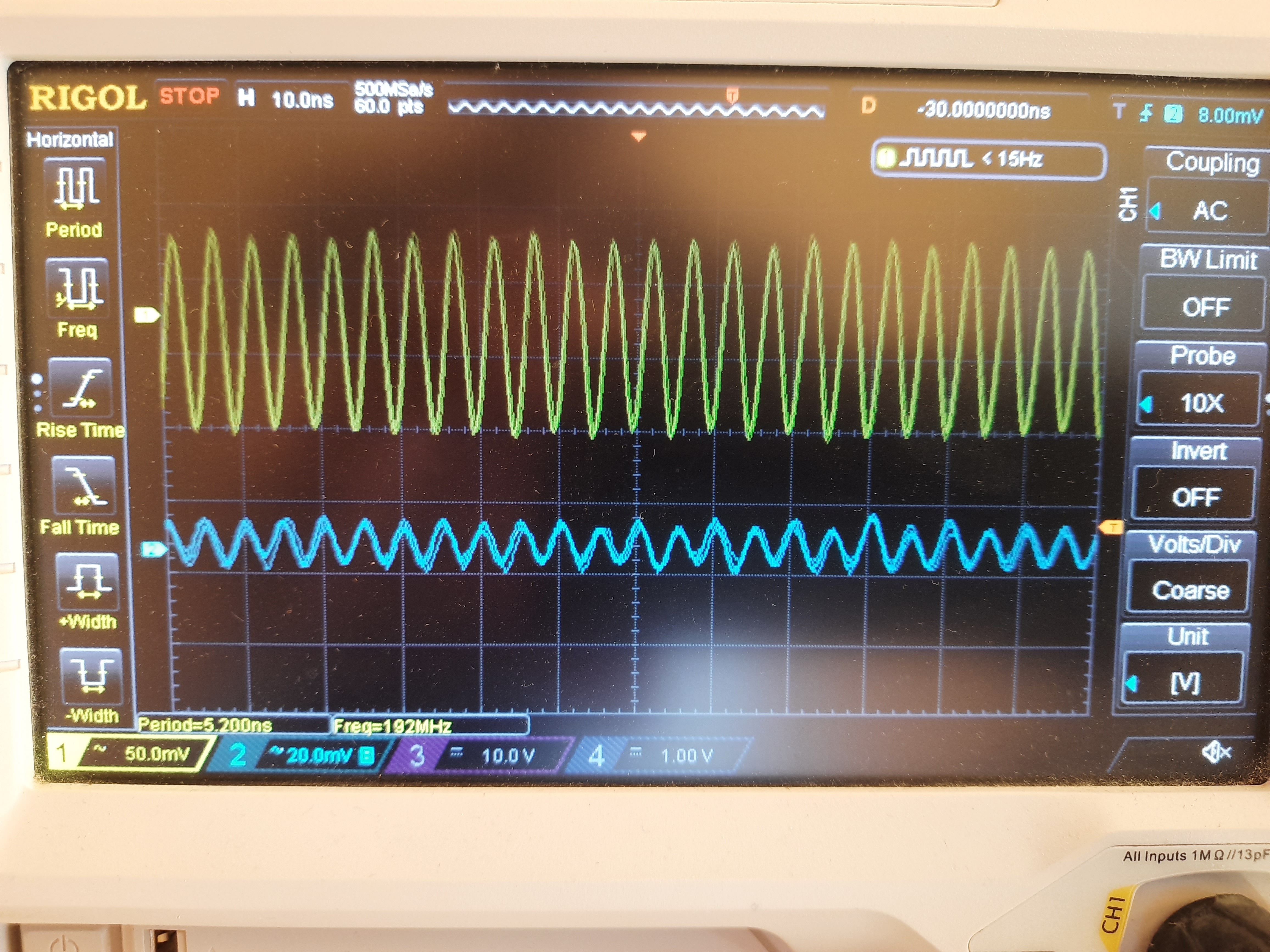
On top the 25 MHz signal. Time base is selected to inspect 25 MHz signal curve. The blue signal is the demodulated signal - nothing of interest can be seen at 20ns/section.
 (click to view larger version)
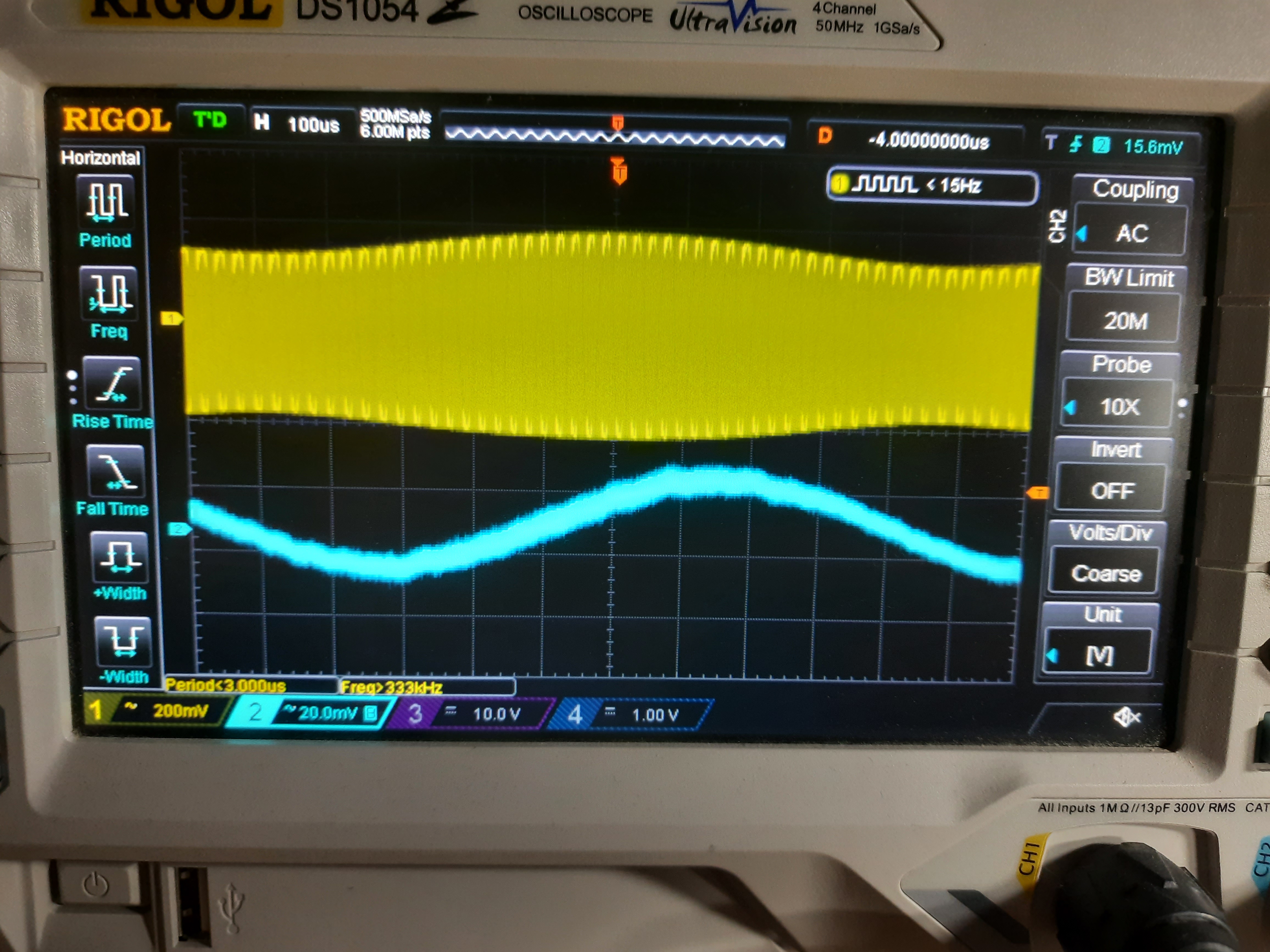
Here I have changed the time base to 100us/section. We can see AM modulation in the 25 MHz signal in yellow curve. We can also see the demodulated 1 KHz signal in blue curve.
 (click to view larger version)
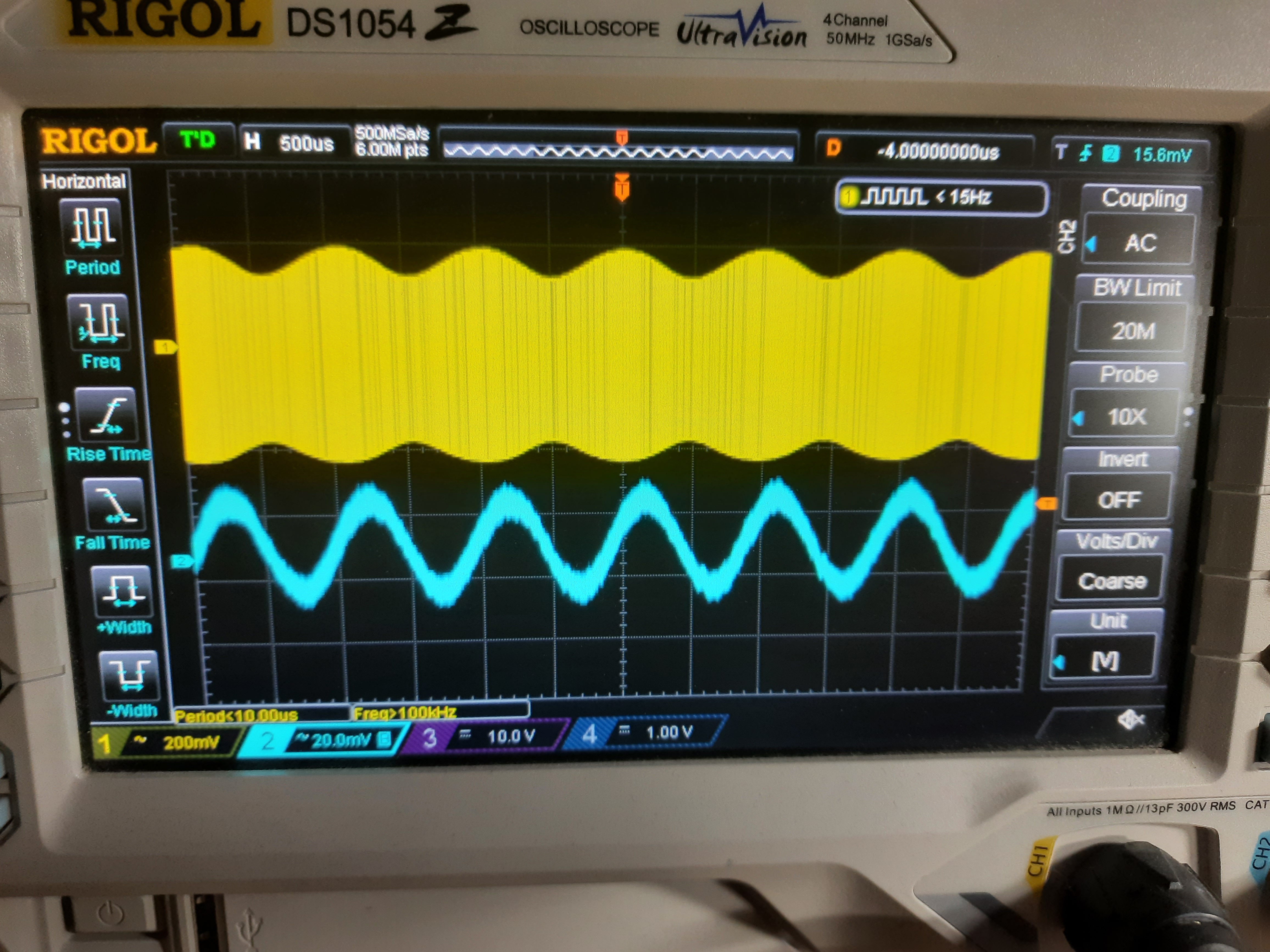
Timebase is now 500us/section. We can see more of the signals.
 (click to view larger version)
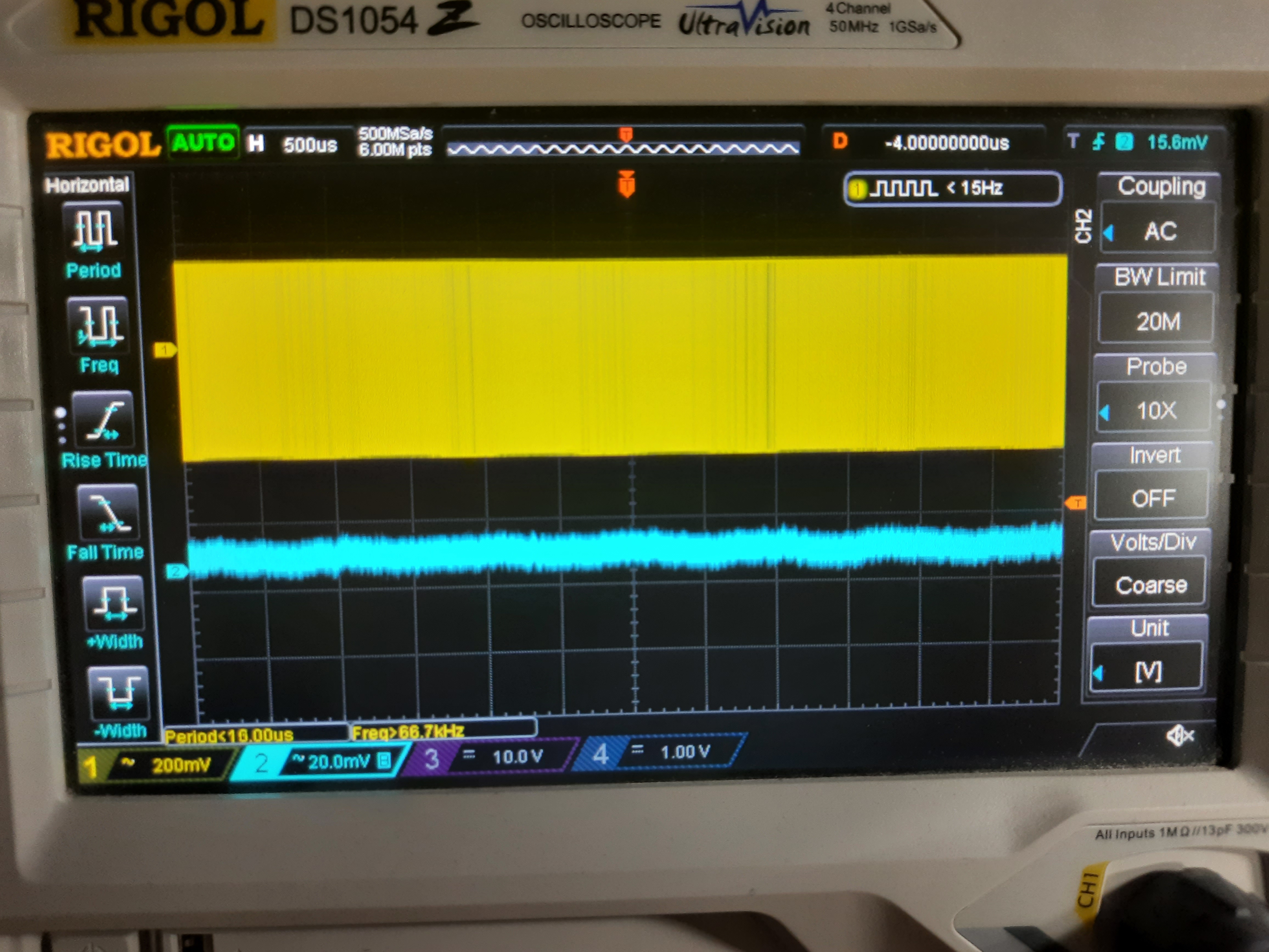
I moved the modulation from AM to FM. The HF-Probe can only demodulate AM signals, so we have no visible modulation (yellow curve) and no output signal ( blue curve).
Finally, I moved to a 200 Mhz signal.
 (click to view larger version)
200 MHz signal, AM-modulated with 1 KHz.
 (click to view larger version)
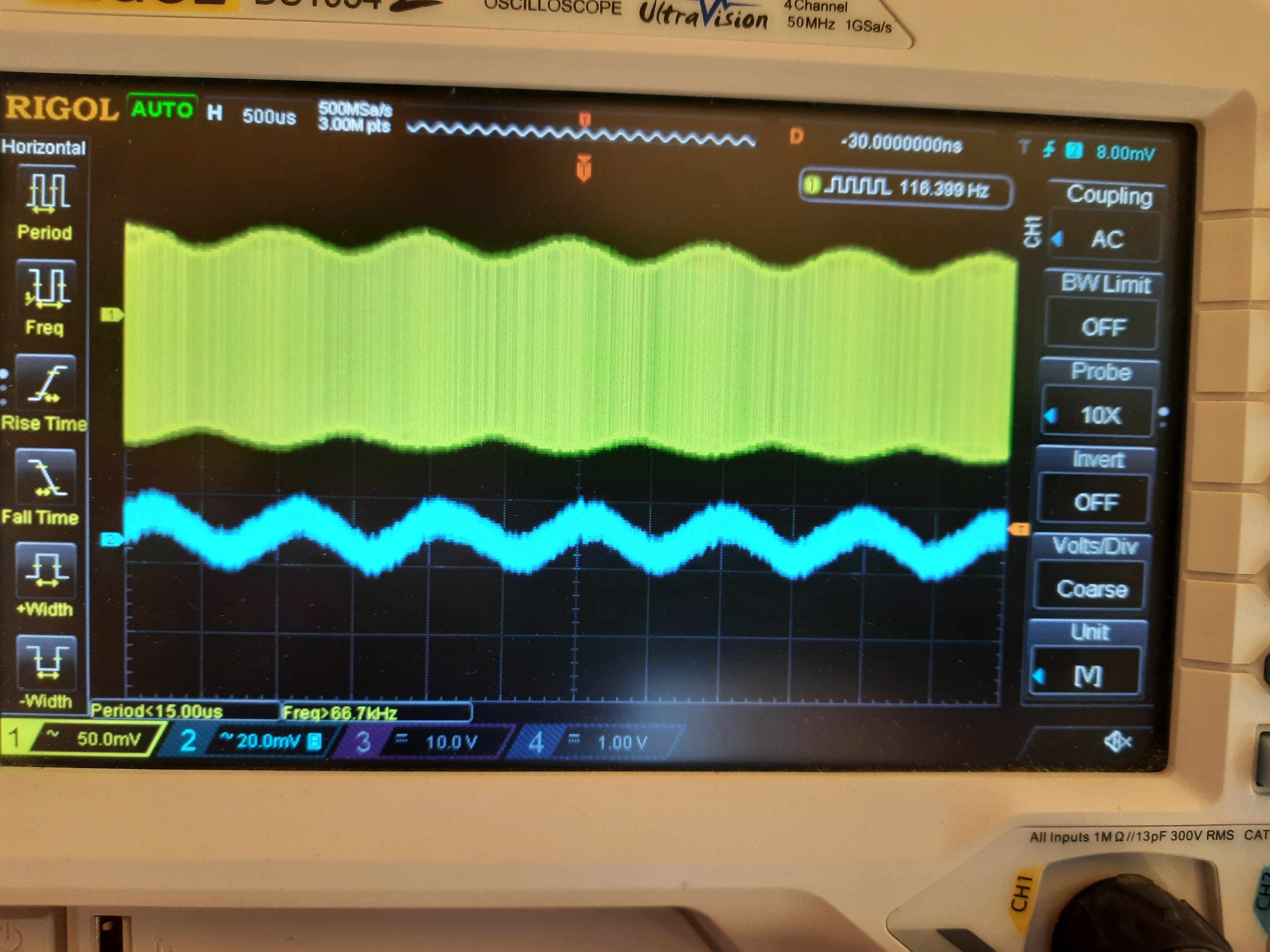
Here I have changed the time base to 500us/section. We can see AM modulation in the 200 MHz signal in yellow curve. We can also see the demodulated 1 KHz signal in blue curve.
The probe schema tested is simple and can demodulate signals in a wide frequency range.