Communication via GPIB with AVR
 Diesen Artikel in deutsch lesen
I have experimented using GPIB together with the AVR microcontroller.
Warning: I describe here -as I do in all my web documents- a lab experiment. I do not describe a method to be used in production environments, neither hardware nor software. The experiments I describe may serve as a base for your own experiments. I am writing this because GPIB-devices are usually expensive. During experiment, it is possible to destroy the GPIB interface of the device. So you have been warned… The GPIB (General Purpose Interface Bus) was developed by HP in the sixties. It was introduced mainly for connecting complex lab equipment for example to do automated testing. The bus system was improved by HP and other companies and standardized as IEEE 488. The GPIB bus is also known as HPIB and IEC 625.
In the area of complex lab equipment, GPIB is after 40 years still widely in use. Especially high end surplus devices from the eighties and nineties often have a GPIB interface.
My oscilloscope Tektronix 2432A of 1989, bought by ebay, has a GPIB interface. The scope can be controlled completely by GPIB, for example all settings can be queried and the stored waveforms can be retrieved. So I tried to connect the scope to my PC.
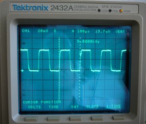
For PCI, USB, ISA and RS232, commercial solutions are available, which server as a bridge between todays PC interfaces and GPIB. These devices are still today very expensive, I haven’t seen any solution below 100 Euro, even used on ebay. So I tried to build my own device with an AVR microcontroller.
GPIB is a parallel bus. Devices can be connected in a daisy chain with special cables, which have a female and a male connector at each end. Each devide has two addresses on the bus (a talker and a listener address). At one GPIB bus, a maximum of 15 devices can be interconnected. One of these devices serves as the “Controller in Charge”. The controller controls data flow between devices using bus commands. On the bus, there can be one one talker at the same time, but there can me many listeners. The device address and the basic behaviour ( listener only, talker only, talker+listener) can be configured usually at the device.
Trivial approach: Talker/Listener Scenario
If there is only one talker and one listener on the bus, no controller is needed. The talker puts his data on the bus without addressing explicit a listener. The listener read all data from bus. This scenario takes place if an oscilloscope is connected to a printer or plotter. I started implemented this scenario first.
Hardware
I took a ATMega32 and connected it in the usual way via RS232 to my PC. The AVR port lines then are connected directly to the GPIB bus. Doing this, some things have to be taken into account. This is described below.
The signal lines of GPIB bus
The GPIB bus uses a 24-pin centronics interface. 8 lines (DIO1..8) are for the data bytes. Three lines (DAV, NRFD and NDAC) are for the handshake on the bus. 5 lines (ATN, SRQ, EOI, REN, IFC) are for bus management. This means that in total 16 lines are required. The remaining lines are ground lines.
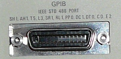
The lines are “open collector” and “active low”. This means a logical “0” means that the signal is set. A logical “1” means that the signal is not set. “Open Collector” means that several listener can share the lines and can set a line independent from the the other listeners without destroying their output drivers. As long as there is only one talker and exactly one listener and in total only two devices, the “open collector” topic can be ignored.
I put the 8 data lines to one port (Port A) of the AVR. I ignored the management lines in the first step and used only the handshake lines, which i put to further three ports of the AVR. So I used 11 lines in this scenario.
Software
The three wire handshake on the GPIB bus is described at many places in internet ( e.g. here) . I will not describe it again.
After implementing the handshake I realized that I do not recognize the end of a data transmission in all cases. The GPIB bus uses the EOI line for that. The talker sets this line during sending the last byte of a transmission. I have not used this line so far. My scope can be configured to send also a CR at the end of all transmissions, so I was saved in that case. For sending binary data, this is not a solution.
The following paragraph shows the output created by the implementation described. The waveform received from the oscilloscope is a square wave. The settings for y-axis of channel 1 and further settings are sent before the waveform itself as the block following WFMPRE. The waveform is sent as block after CURVE. Values about 50 are the Ones from the signal, values about 0 are the zeroes. For better viewing, i split the single curve line into several lines.
WFMPRE WFID:"CH1 DC  20mV  10ms
NORMAL",NR.PT:1024,PT.OFF:512,PT.FMT:Y,XUNIT:SEC,XINCR:2.000E-4,YMULT: 8.000E-4,YOFF:0,YUNIT:V,BN.FMT:RI,ENCDG:ASCII;
CURVE 0,0,-1,0,0,1,-1,0,0,0,1,1,49,50,50,50,49,49,50,51,49,
50,50,50,50,51,50,50,50,50,50,50, 50,51,50,50,50,52,50,52,
50,49,51,51,50,50,50,49,50,50,51,52,50,52,49,50,50,51,50,
50,51,50,0, 0,1,1,-1,0,0,0,-1,0,-1,-1,-1,0,0,-2,0,0,0,0,0,
-1,-1,1,0,0,-1,0,1,0,1,0,1,-1,1,1,-1,0,1,0,0,1,1,0,1, 0,
-1,1,-2,0,50,51,50,50,49,51,52,50,51,51,50,50,51,50,52,49,
51,52,51,50,51,50,52,50,51,52,50, 50,49,51,50,51,50,50,51,
50,52,49,51,51,51,51,49,50,52,51,50,50,51,51,2,0,1,-2,0,-1,
1,-1,0,1,0, 0,0,-1,-1,1,0,-1,1,0,0,-1,0,-2,1,0,0,-2,0,0,-1,
-1,0,1,-1,-1,-1,0,0,-1,-2,-1,-1,1,-1,1,0,1,-2,-1,49,49, 48,
51,50,50,50,50,49,52,51,51,52,50,50,51,49,49,51,50,51,50,
50,49,50,51,51,51,51,51,51,50,50, 50,52,51,51,50,50,50,51,
50,51,52,52,51,51,52,50,50,1,-1,0,0,1,0,-1,-1,1,-1,1,-1,-1,
0,0,1,0,0,-1, -1,-2,-1,1,0,0,-1,1,-1,1,-2,-1,-1,-1,-1,0,1,
1,1,-1,1,-1,1,-1,-2,0,-1,-1,-2,1,0,50,50,50,50,50,50,50,
51,51,50,51,50,50,50,49,51,51,50,50,51,51,50,51,50,52,52,
50,51,50,50,51,50,50,51,50,50,51,50, 51,51,51,50,50,51,49,
49,51,49,49,50,0,0,0,-1,0,-1,1,0,0,-1,0,0,-1,0,0,1,-1,0,-2,
0,0,0,-1,-1,-1,-1, 0,0,0,-1,-1,0,-2,0,-1,0,-1,0,0,-1,0,0,
-1,0,-1,0,0,-2,-1,0,49,50,49,50,49,51,50,50,51,50,51,50,
50,49, 50,52,52,49,48,51,51,50,50,51,51,51,50,50,51,52,50,
50,51,51,50,51,51,50,49,51,50,50,52,50,52, 50,49,50,50,50,
0,0,0,0,0,0,-1,0,0,0,0,0,0,-1,-1,-1,0,1,1,-1,-1,0,0,0,-1,
-2,0,0,1,0,-1,1,1,0,0,1,-1,-1, 0,-1,0,-1,2,0,0,0,-3,0,1,
0,50,50,51,49,51,52,50,49,50,51,50,50,50,51,51,50,51,51,
51,52,49,50,49, 50,50,49,51,53,49,51,50,48,51,51,51,50,49,
51,51,49,51,50,52,51,50,50,50,51,52,50,-1,-1,0,0,-2,-1,
-1,-1,0,-2,-1,-1,-1,0,0,-2,0,-1,0,-1,-1,-1,0,-1,-1,0,0,
-2,0,0,-1,1,0,-3,0,0,-2,0,-1,-1,0,0,-1,0,0,0,-2,-1,
0,-1,50,50,51,49,51,49,50,51,50,50,50,50,49,51,51,50,51,
51,50,51,50,49,50,51,50,50,49,50,52,50,51, 50,49,50,51,51,
50,51,50,52,50,51,52,50,50,50,50,51,51,51,-1,0,0,-1,0,0,0,
0,-1,0,0,1,-2,0,0,-1,0,0,0,0, -1,0,-1,-1,-1,0,0,0,1,-1,0,0,
-1,0,-1,0,-1,-1,1,1,0,0,-1,0,-1,-1,-1,-1,1,0,50,51,50,51,
51,50,50,51,50,51,49, 52,50,50,50,51,50,51,49,51,52,50,51,
50,51,50,51,52,48,49,49,50,48,49,50,51,50,50,50,50,50,50,
51,49, 50,51,48,50,51,52,0,0,0,0,0,0,-2,0,0,0,0,-1,-1,0,
-1,0,0,-1,0,1,0,-1,-1,-2,0,0,0,0,0,-1,1,0,0,-1,0,-1,-1,1,
0,0,0,-1,0,-1,0,0,0,-1,-1,-2,49,50,50,52,50,49,50,50,49,
50,52,50,49,50,51,52,49,49,49,51,51,50,50,50,50,49,51,
50,50,50,51,52,50,50,50,50,50,50,49,52,51,50,50,50,51,52,
50,50,52,49,0,-1,0,-1,0,1,2,-1,-1,-1,0,1, 0,-1,0,0,1,0,0,
-1,0,1,0,0,-2,0,-1,-1,0,-1,-1,-1,0,-1,0,-1,0,-1,0,0,1,-1,
-2,-1,-2,1,-1,-1,1,1,50,48,49,49,49, 50,50,51,50,51,50,
50,52,50,51,52,51,51,52,50,52,49,50,49,51,49,52,50,50,50,
48,51,50,50,49,51,51,50,51, 50,50,48,50,52,51,49,50,50,
49,51,0,-2,-1,-1,1,0,0,0,0,1,-1,-2,0,1,0,-2,-1,0,0,0,
-1,-1,0,0,0,0,-2,1,0,-1,-1,-1, -1,0,-2,-1,-1,0,-1,-1,
-1,-1,0,-1,0,-2,0,0,1,-2,49,50,51,51,49,50,52,51,50,51,
52,51
This means that it is possible to read data from a GPIB device using an AVR and a PC. In the scenario, no commands can be sent from PC to GPIB device. This would require the extension of the existing code by controller functionality and to use more lines from the GPIB interface. Besides this, the topic “Open Collector” must be solved as described above. If not, the output driver of either the AVR or the oscilloscope may be destroyed. The controller approach is described further below.
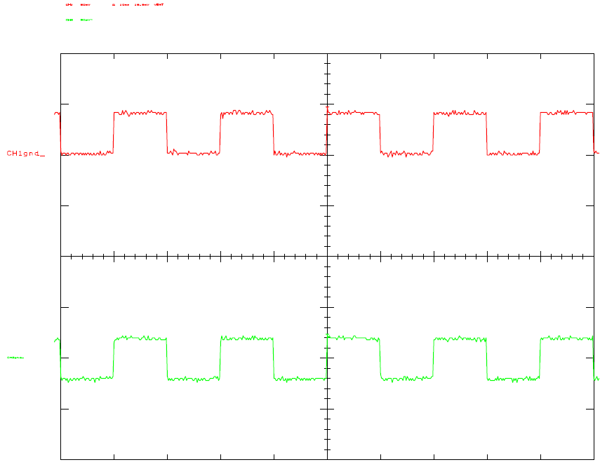
My scope is able to produce wave forms in HPGL format. Below is an example output in HPGL (not complete):
in;sc-690,689,-512,511;
sp1;
pa-500,-400;pd;pr1000,0,0,800,-1000,0,0,-800;
tl1;xt;pr100,0;
tl1;xt;pr100,0;
tl1;xt;pr100,0;
tl1;xt;pr100,0;
tl1;xt;pr100,0;
tl1;xt;pr100,0;
tl1;xt;pr100,0;
tl1;xt;pr100,0;
tl1;xt;pr100,0;
tl1;xt;pr100,0;
tl0,1;yt;pr0,100;
tl0,1;yt;pr0,100;
tl0,1;yt;pr0,100;
tl0,1;yt;pr0,100;
tl0,1;yt;pr0,100;
tl0,1;yt;pr0,100;
I converted this output with the open source tool “hp2xx” in a jpeg and a PDF file. The output can be captured e.g. with kermit log session feature (“log session ”). The following command sequence creates a well looking PDF output:
rm -f tmp.eps out.pdf
./hp2xx -p 22222222 -C -o 20 -O 150 -h 100 -a 2  -m eps -d 600 $1 -f tmp.eps     ps2pdf tmp.eps out.pdf
acroread out.pdf
Curve and scales are ok, but legend strings are too small. Using option “-d ” , the DPI-resolution of the result can be increased. Starting with about 300 DPI, the legend strings can be read.
Tests with another tool called hpgl2ps were even worse.
Elaborated Approach: Talker/Listener Scenario
To move forward, I connected also the GPIB lines EOI, ATN, SRQ, IFC and REN to AVR ports. The port connection table is listed below:
| GPIB Pin Name | GPIB-Interface Pin Nummer | ATMega32 Pin Name | AVR Board Interface Pin Nummer |
|---|---|---|---|
| DIO1..8 (Datenpins) | 1..4 und 13..16 | PortA0..PortA7 | 1..8 |
| EOI | 5 | PD4 | 30 |
| DAV | 6 | PD2 | 28 |
| NRFD | 7 | PD3 | 29 |
| NDAC | 8 | PD5 | 31 |
| SRQ | 10 | PD6 | 32 |
| ATN | 11 | PD7 | 33 |
| IFC | 9 | PB0 | 9 |
| REN | 17 | PB1 | 10 |
| GND | 23 | GND | 39 |
Usage of EOI signal
Checking the the EOI-signal with a second scope showed, that the signal is without transmission LOW, during the transmission HIGH and after the last byte LOW again. This seems to be different from all descriptions I found in the internet. There it is stated that the signal is LOW only during transmission of the last byte.
Using AVR pins with “open collector” behaviour
The AVR microcontroller is extremely flexible, but the port pins can’t be switched directly to a open collector mode. It is possible to put open collector bus transceivers like 74245 in front of the AVR, but I am lazy. Internet search shows that the open collector behaviour can be emulated with standard AVR pins. The port is set to LOW and the output (LOW or HIGH) is controlled by the DDRx data direction register. For example PORTD and Pin PD4:
| Function | “common” use | Open collector emulation use |
|---|---|---|
| Initialisation of Pin | DDRD OR= _BV(PD4) // as output DDRD &= ~BV(PD4) // as input | PORTD &= ~_BV(PD4) DDRD &= ~_BV(PD4) |
| Set Pin to HIGH | PORTD OR= _BV(PD4) | DDRD &= ~_BV(PD4) |
| Set Pin to LOW | PORTD &= ~_BV(PD4) | PORTD &= ~_BV(PD4) DDRD |
| Read Pin value | unsigned char p = PIND & _BV(PD4) | DDRD &= ~_BV(PD4) unsigned char p = PIND & _BV(PD4) |
After changing the code according to the table, my code still works. So the controller implementation is the next step to do.
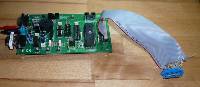
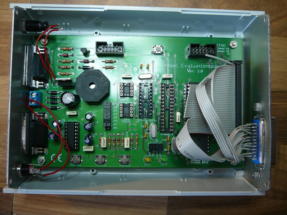
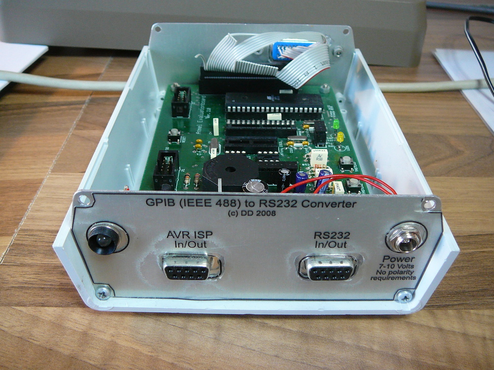
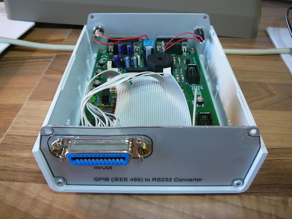
The experimental board from the german company Pollin. Of course, every other board can be used, as long as enough port pins are available. Connectivity to this board is done via a 40-pin IDE connector, I attached an old IDE cable and soldered the GPIB connector to it.
GPIB Controller Implementation
This part is a little bit tricky, because the information on internet is not really clear.
The controller initially takes over the bus and controls all devices connected to the bus. this means he defines them als listener, talker or not participating in the actual transfer. For this, the controller uses management lines (like IFC and REN) and also bus commands (like DCL, UNL, UNT). The controller distinguishes command bytes from data bytes by assigning the ATN line during transmission of command bytes. When ATN is assigned, the talker device stops talking and all devices listen to the commands transfered on the bus.
Devices become listeners if they are addressed from the controller by their listener address (=device adress + 0x20) and become talkers if they are addressed from the controller by their talker address (=device address + 0x40). There is always zero or one talker, but there may be many listeners at the same time. Controller address is usually (but need not to be) 0x00.
My simple controller implementation works as follows:
- Controller takes over bus by assigning REN and IFC (in functions gpib_init() and gpib_controller_assign()). Then he sends DCL command (using gpib_cmd()). All devices go to an initial state.
- Execution of a endless loop:
- Read in commands from STDIN. A CR is interpreted as end of command line. Then the controller switches itself to talker und a (selectable) device to listener (for example my scope with device address 0x01 becomes listener by receiving its listener address 0x21). The command line read from STDIN is written to the bus (gpib_write()). The controller uses EOI line to communicate end of transmission.
- Listener reads in command and executes it. There are two types of commands: one way commands where no answer is expected and commands with an answer. The controller distinguishes these command types by checking if a ‘?’ is part of command. If yes, it is assumed that it is a command with answer. If not, it is assumed that it is a one way command. This interpretation is at least true for device from Tektronix. I have only Tektronix and can not test for other devices. For commands with no answer, the loop starts again For commands with answer, the controller becomes a listener and sets the device to be a talker (gpib_cmd()). Then the controller reads in the answer and prints out every byte to STDOUT. The device communicated end of transmission by assigning EOI line. Then the loop starts again.
- Besides the loop, the controller also has a asynchronous behaviour: A device can initiate a service request SRQ. This is done by the device by assigning the SRQ line. The device may signalize by SRQ that it wants e.g. transfer data to the bus. The controller then initiates a “serial poll” by sending the SPE command (serial poll enable). It addresses each known device as talker and reads data from device. The device goes in a special mode when receiving SPE, meaning it send a status byte if addressed as talker. By examining bit 6 of the status byte, the controller can find out the SRQ emitting device because this device sets the bit to 1 and all other devices have it set to 0. Having found the service requesting device, the controller ends serial poll with command SPD (serial poll disable). Handling the SRQ is device dependent. For example, my scope communicates with an errorcode like “157” errors in commands received (misspelling etc.).
- In theory, the controller releases bus at the end (gpib_controller_release()) .
During GPIB handshake, the controller may wait forever if there is an error in communication or the device was switched off. I added timeout code, so the controller recognizes a timeout and returns to the global loop.
Below, a session is shown. If the scope is switched on, it generates a SRQ. The controller asks the device for SRQ reason using “EVENT?” command. The answer by the scope is “401”. 401 means according to scope manual “2432A was just powered on.” which is correct. Then the command “id?” is entered, the scope returns his id. After that, some commands are sent to the scope.
INIT MEASUREMENT WINDOW:ON CURSOR FUNCTION: TIME,TARGET:CH1,UNITS:BASE CURSOR TPOS:ONE:200,TPOS:TWO:500
Finally settings for channel 1 are queried.
dennis@soc:~> kermit -c
Connecting to /dev/ttyS2, speed 19200  Escape character: Ctrl- (ASCII 28, FS): enabled
Type the escape character followed by C to get back, or followed by ? to see other options.
----------------------------------------------------
SRQ detected. status byte from device 0x41 = 0x41 (char=A)
SRQ emitter is device = 0x41
command: EVENT?
Query. Will check for answer.
EVENT 401
> id? command: id?
Query. Will check for answer.
ID TEK/2432A,V81.1,"24-DEC-89  V2.30 /2.5"
> INIT
command: INIT
Command only.
> MEASUREMENT WINDOW:ON
command: MEASUREMENT WINDOW:ON
Command only.
> CURSOR FUNCTION: TIME,TARGET:CH1,UNITS:BASE
command: CURSOR FUNCTION: TIME,TARGET:CH1,UNITS:BASE
Command only.
> CURSOR TPOS:ONE:200,TPOS:TWO:500 command: CURSOR TPOS:ONE:200,TPOS:TWO:500 Command only.
> CH1?
command: CH1?
Query. Will check for answer.
CH1 VOLTS:1E-1,VARIABLE:0,POSITION:0,COUPLING:DC,FIFTY:OFF,INVERT:OFF
>
Result: the controller implementation based on AVR works quite good. For a real production version the software should be extended and tested with many more devices.
Below I provide the software under General Public Licence as ZIP file. The ZIP file includes the files uart.h/uart.c from peter Fleury for RS232 handling. This library is also under GNU GPL.
ZIP file with all files including docs: gpib-rev689.zip
Version history:
- 0.689 Improved the still spartane command line user interface, improved stability
- 0.66: Added doxygen documentation, see directory doc
- 0.63: Communication with two (and maybe more) devices works. A error in the read function was removed.
- 0.1: Communication with a single device (Tek 2432A tested) works ok.
A complete session log with version 0.66 can be found here: Session with 2 devices The used devices were scope Tektronix 2432A and Logic Analyzer Tektronix 1241.
For some (homebrew, experimental) additional software that is able to display captured data from the Tektronix 1241, see here .
Prototype
Some photos of the prototype mounted into a case.
Related Links
- http://members.fortunecity.com/ultravinnie/electronics/gpibfaq/gpibfaq.html
- GPIB FAQ, good start
- http://www.fysik.uu.se/kurser/fy660/compendium/GPIB/
- good overview, connector diagram, handshake diagram, GPIB commands, polling
- http://www.hit.bme.hu/people/papay/edu/GPIB/tutor.htm
- GPIB Tutorial
- http://www.interfacebus.com/Design_Connector_GPIB.html
- another intro
- http://www.physics.brocku.ca/~edik/gpib/
- Diverse GPIB Links
- http://www2.informatik.hu-berlin.de/~menze/download/ti1d/ti1d7.pdf
- GPIB-Handshake
- http://zone.ni.com/devzone/cda/tut/p/id/4056
- serial polling
- http://hpux.cs.utah.edu/hppd/hpux/Gnu/hp2xx-3.4.4/
- hp2xx Tool, converts HPGL in diverse graphic formats, runs under Linux
- http://www.thegleam.com/ke5fx/gpib/readme.htm
- Interesting Software (Windows) , GPIB card required
- http://home8.inet.tele.dk/jan_p/micro/micro1.htm
- Coupling AVR <-> GPIB with BASIC code
- http://lpvo.fe.uni-lj.si/gpib/ - project USB<-> GPIB
