Epson HX-20
EPSON HX-20
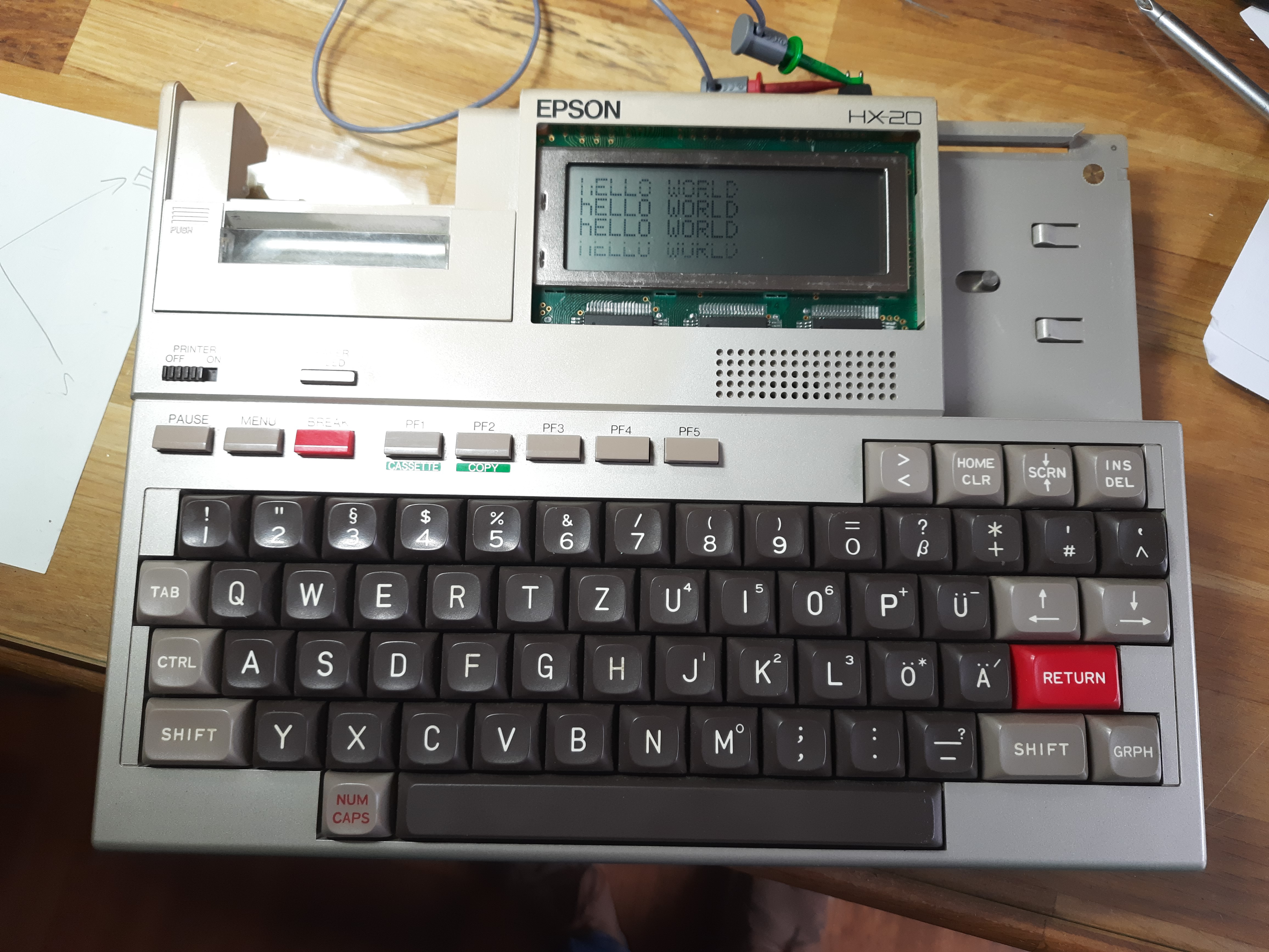
This is an interesting machine from the early 80s. It has a notebook form factor and a nice complete keyboard with real keys. At that time, large LCDs were not available, so it has a small LCD with 120x32 pixels. This gives 4 lines of text with 20 characters. It includes a built-in miniature printer and a miniature cassette drive for mass storage.
This machine is extendable in many ways, with additional RAM and ROM modules, external monitor (then with more display space), and some other serial devices like barcode reader and what not.
First image shows my device, which arrived with broken LCD PCB. more on that later. Both printer, cassette drive and other parts are removed in the picture.
Images from inside
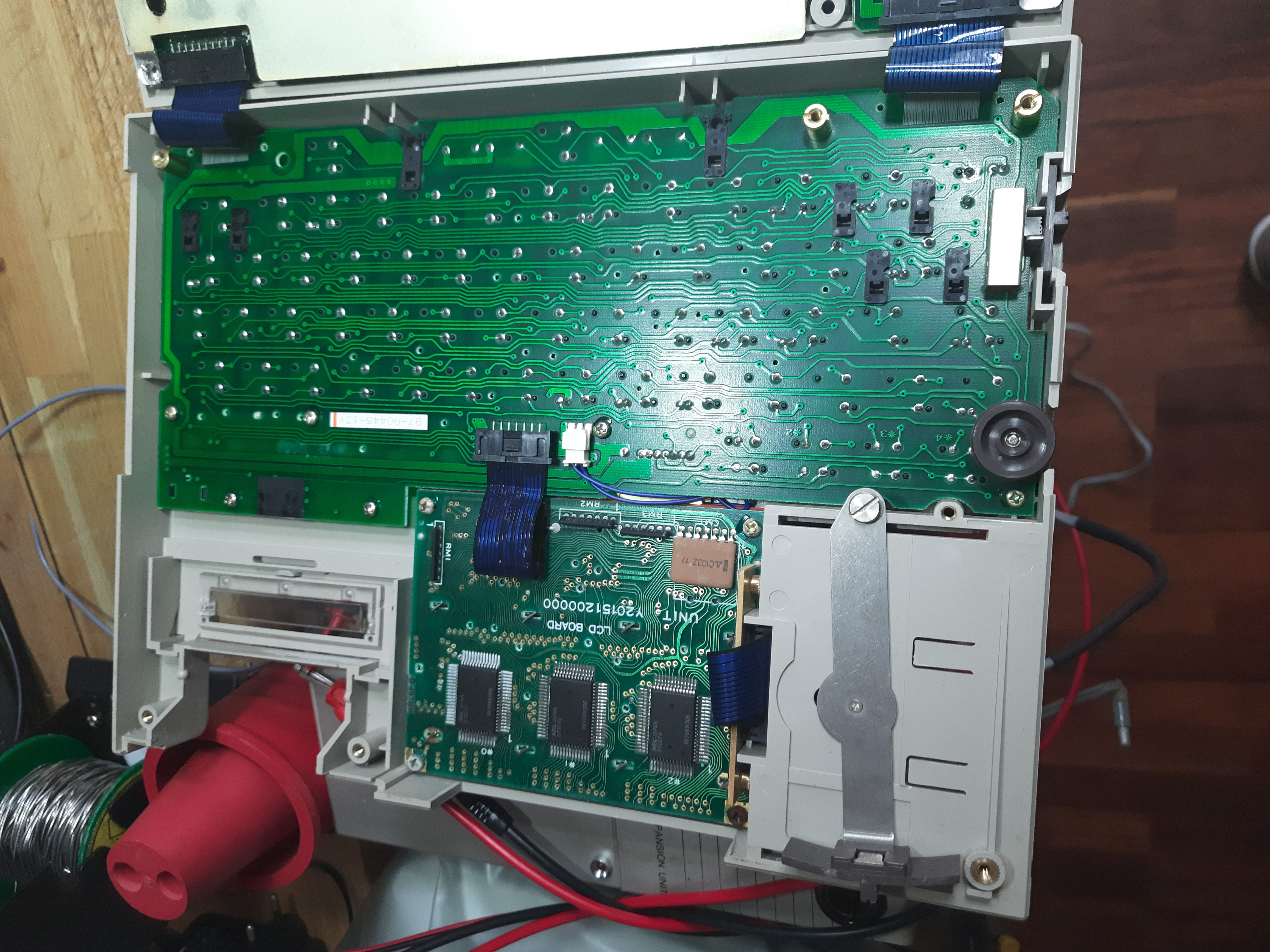
Keyboard and LCD PCB:
Mainboard soldering side. At bottom left there is space for an extension module:
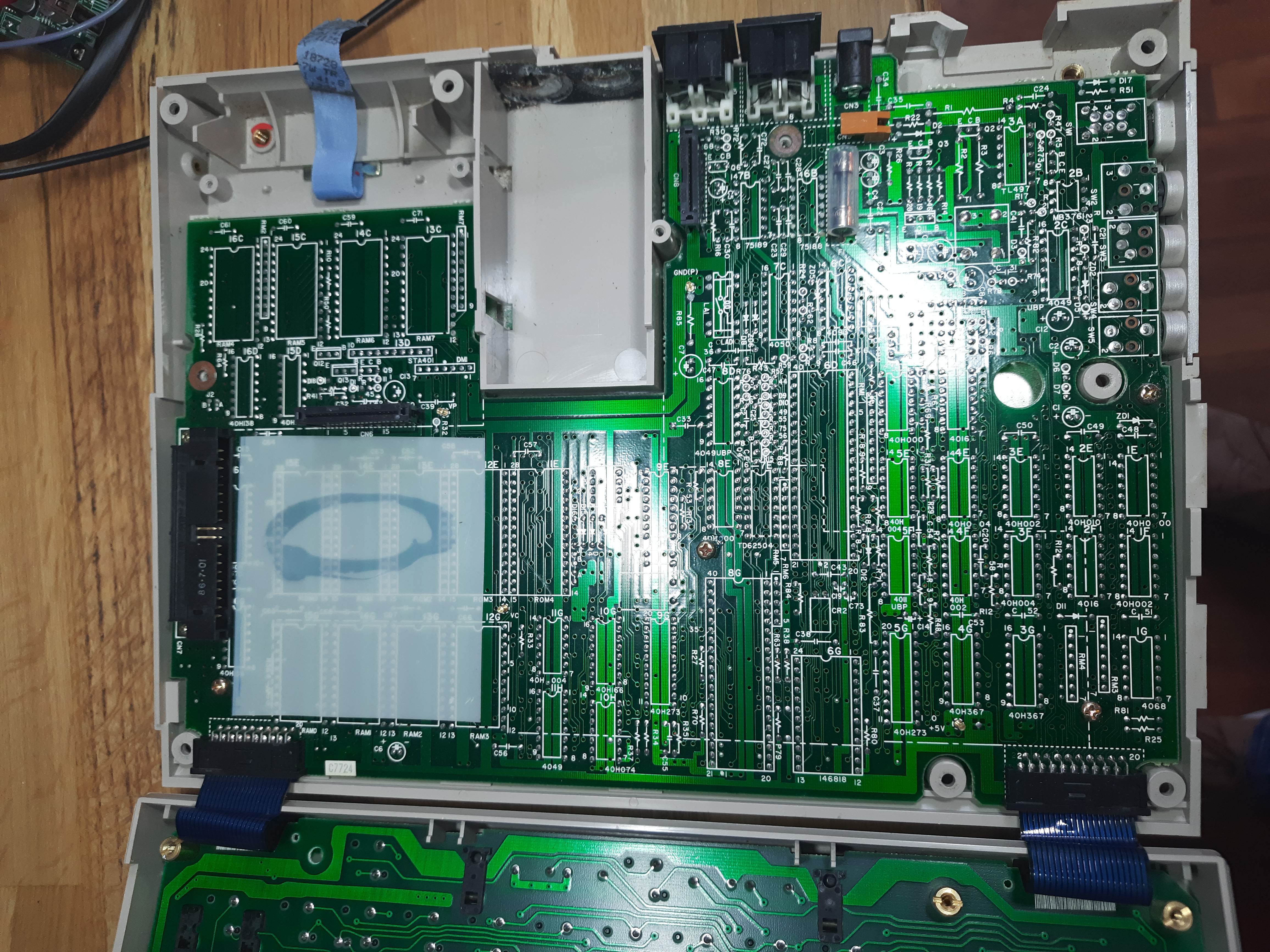
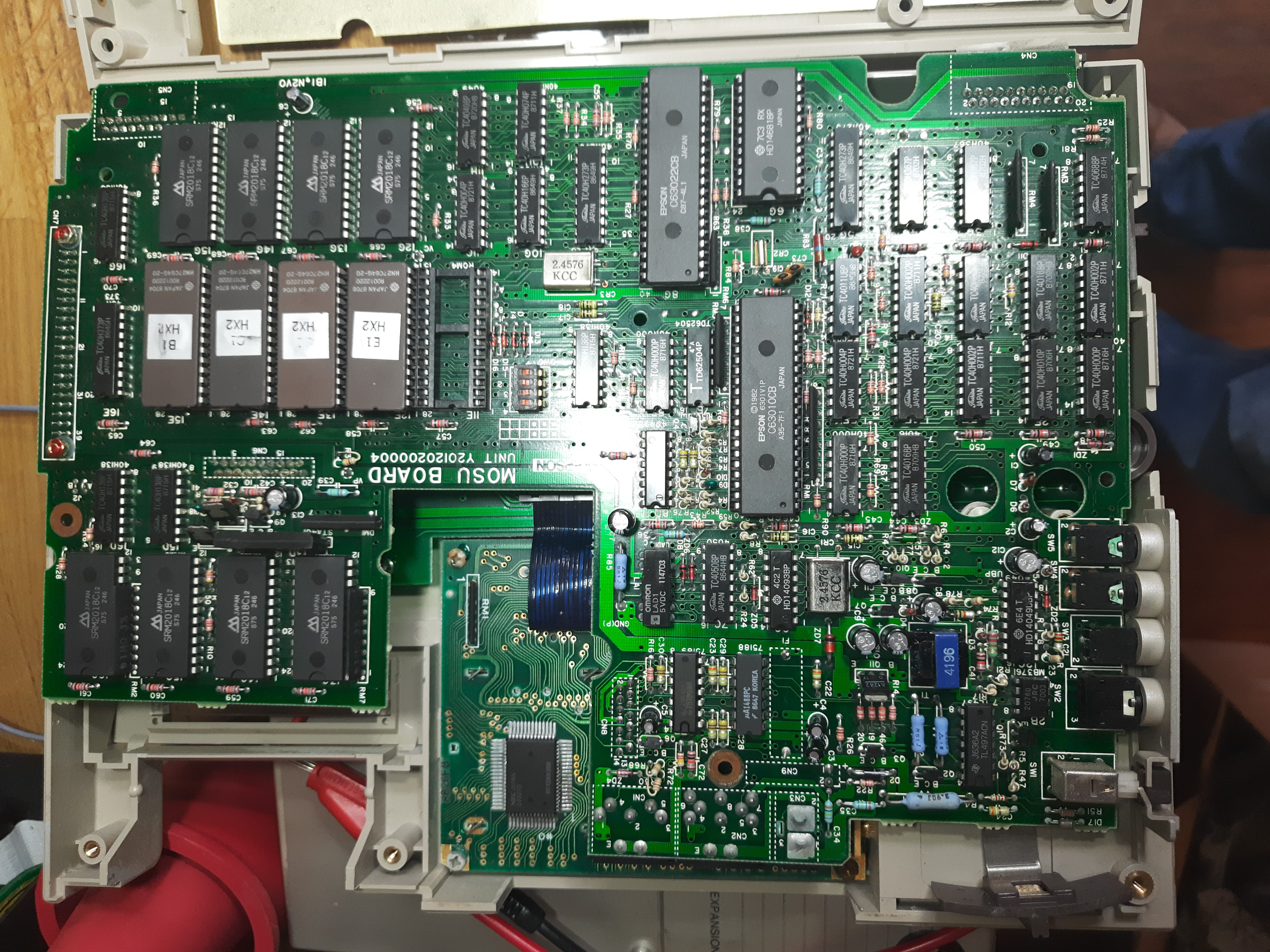
Image below shows mainboard, called “MOSU Board”. Upper and lower left is 8+8K RAM, then 4 EPROMs and a free socket for a fifth EPROM. Two CPUs: on top the slave, more in the middle the master CPU. Both CPUs are the same and of 6301 type (siblings of 6800 design). They run at 614Khz.
The larger chip at the
top right of the slave CPU is a RTC HD14681. All smaller chips are more or less 40xx standard
CMOS for driving cassette module, external interfaces and so on. On the bottom
right there is more or less the power supply section. This has some complexity,
because the device can run from AC adapter, from battery and does keep a
part of the machine always on to keep RAM content even when switched off. Also,
some utility voltages for RS232 voltage and LCD are created. RS232 voltage is
interestingly created with a TL497 PWM controller:
EEPROMS:
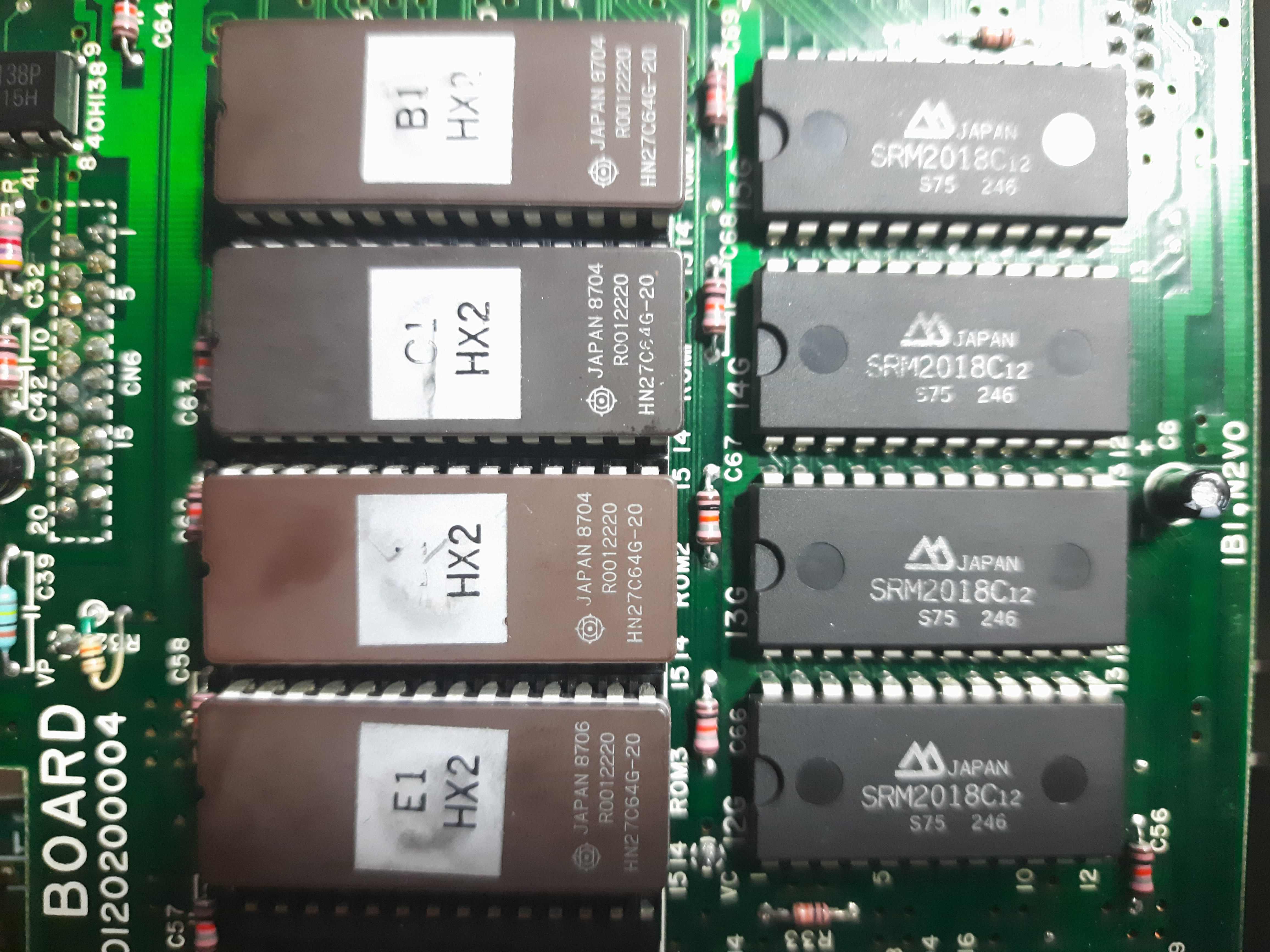
These are 4x8=32KB ROMs. The free slot allows another 8KB ROM to be inserted (somewhere I read that even a 16K ROM is possible).
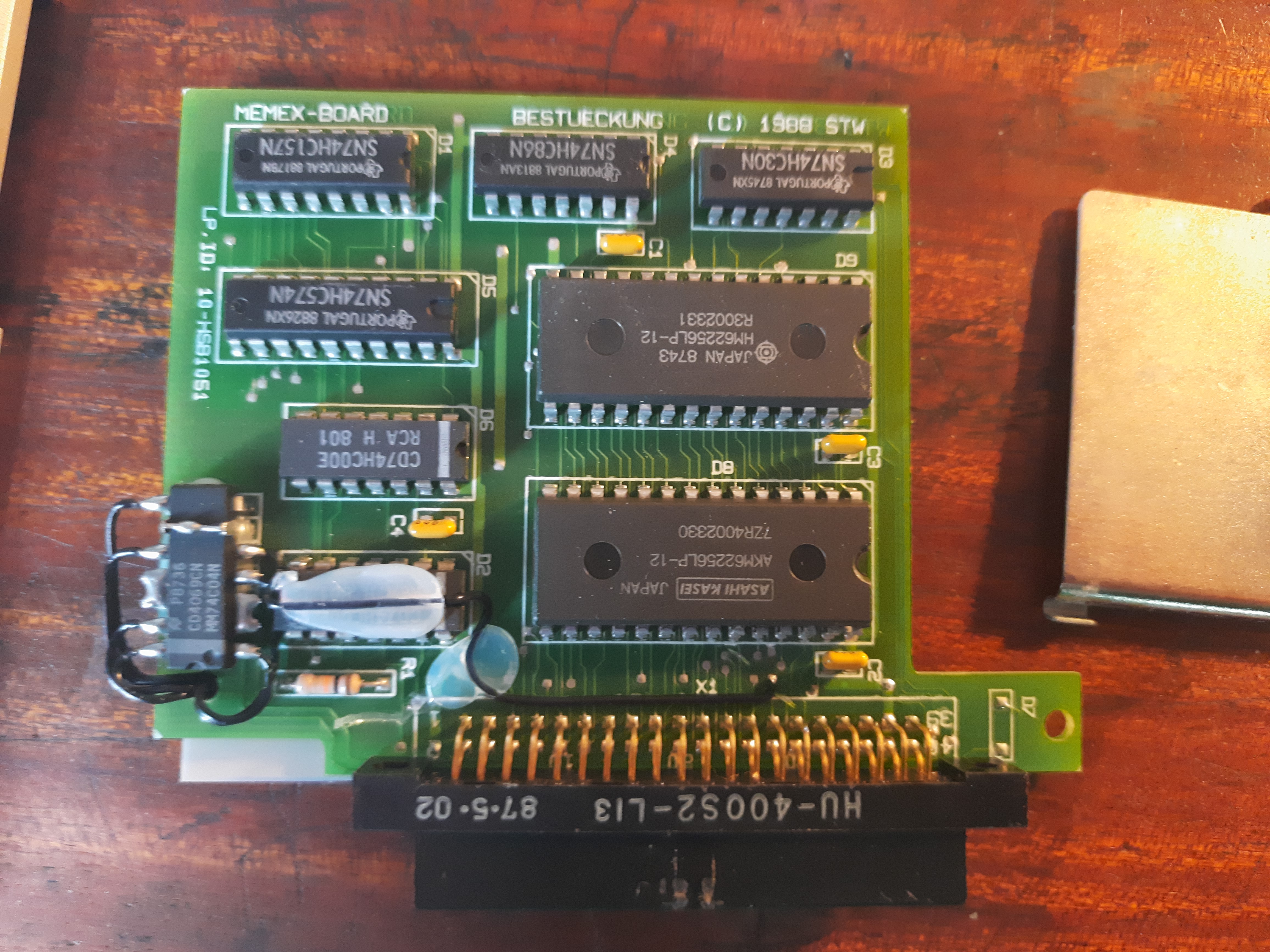
16KB RAM module
Internal module with some handcrafted soldering. This has german words on it “MEMEX-BOARD Bestueckung (C) 1988”, so it looks like not being a genuine epson module.
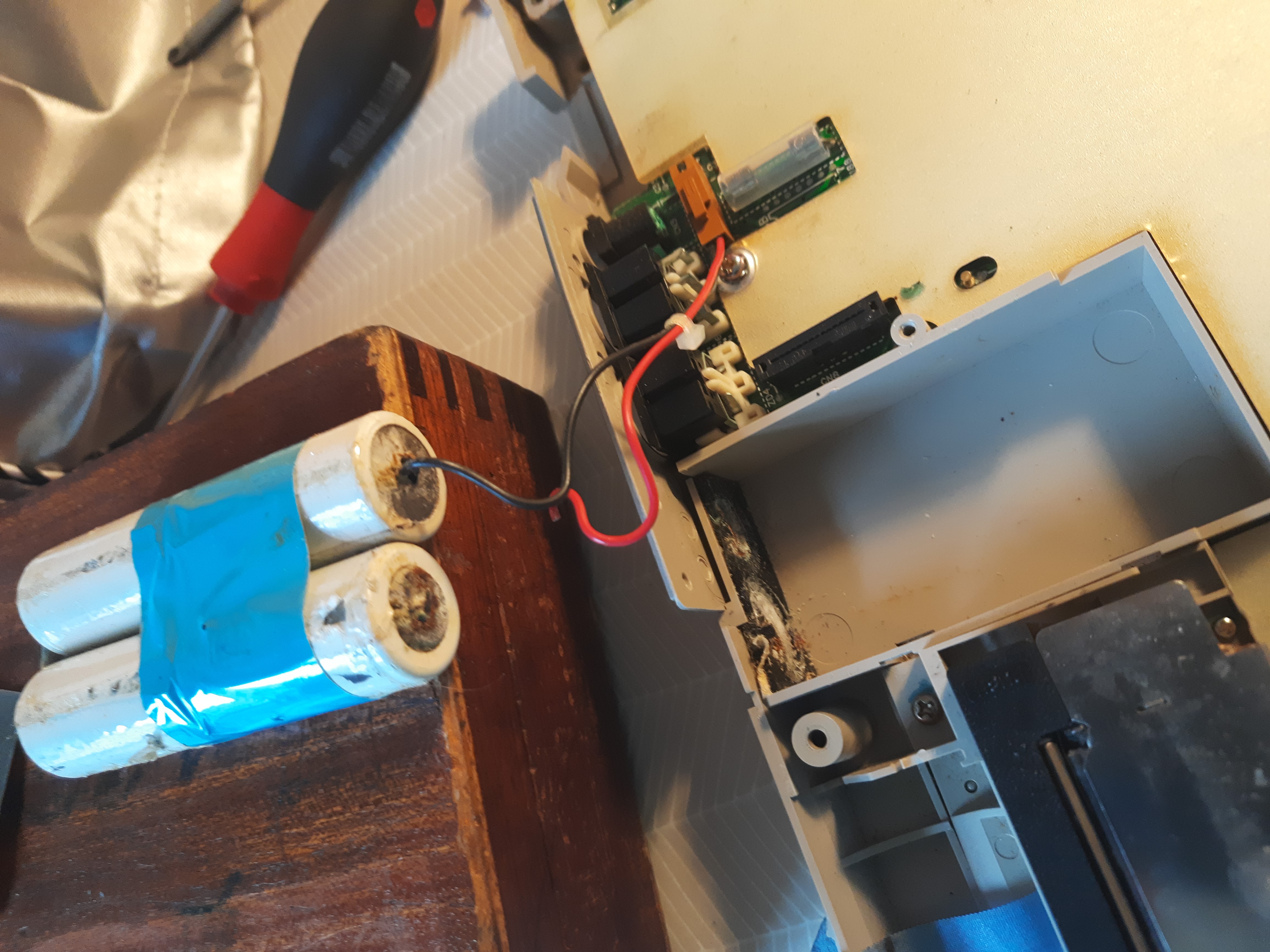
Broken batteries
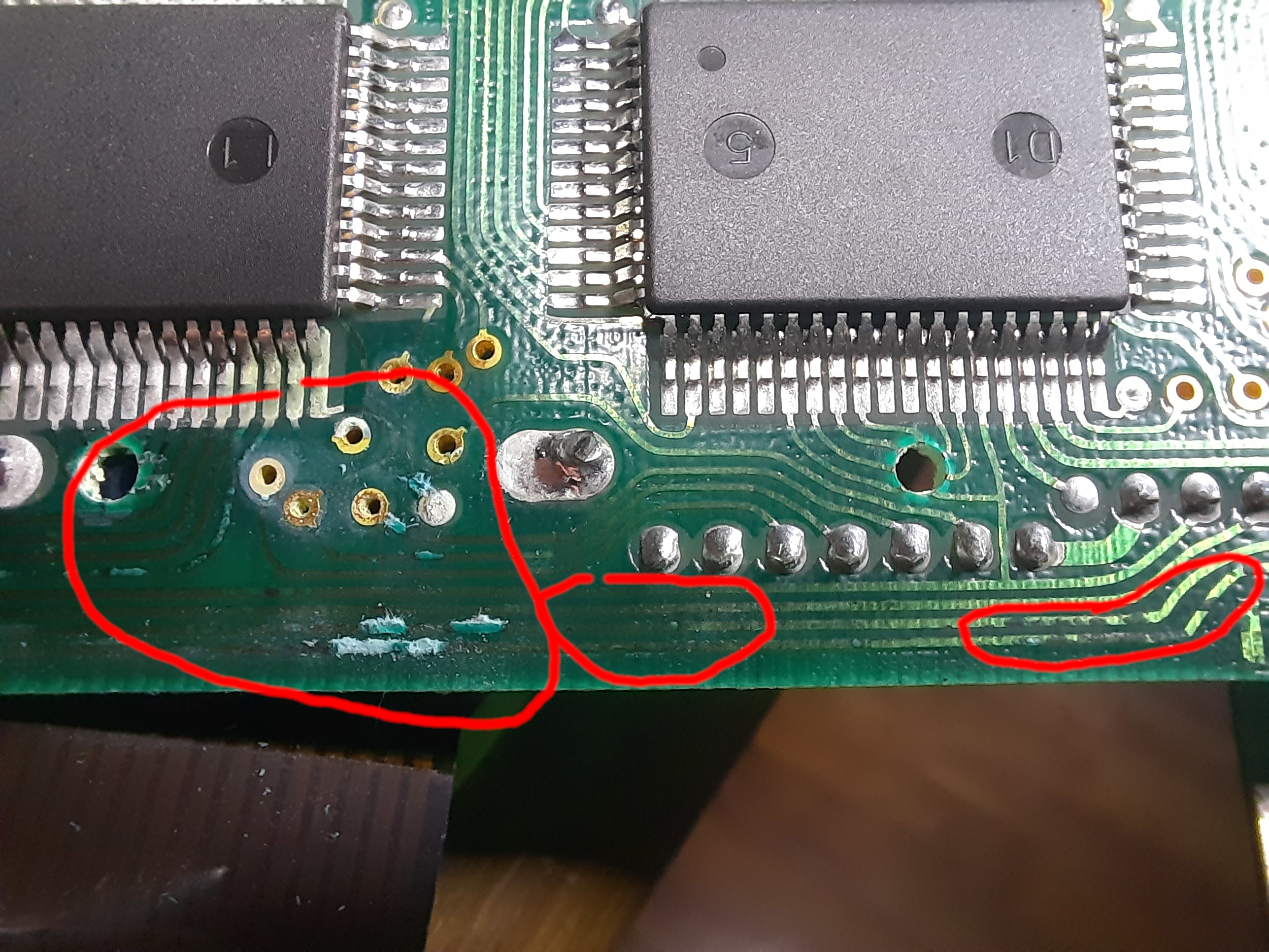
Broken LCD PCB
In most cases, I have luck when buying old computers, they mostly work right on. But this one has a big issue. The leakage of the batteries destroyed traces on the LCD PCB. And not only a single one, but at various places on both sides.
Next image shows some corroded traces and vias, some of them are interrupted by corrosion.
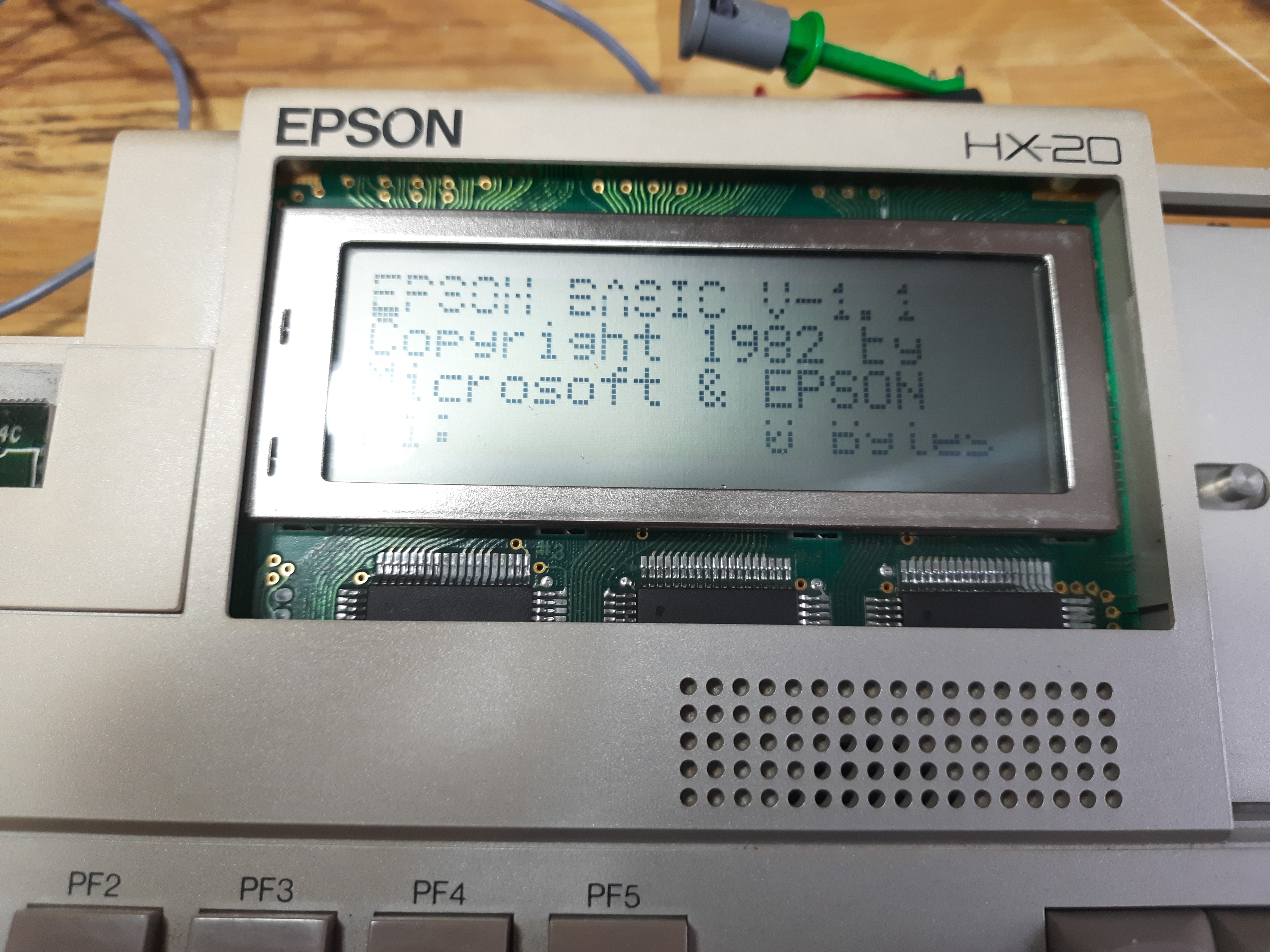
Try to repair LCD PCB
I checked al traces that are reachable. Some traces are below chips and cannot be checked. I found about 20 interruptions in several sessions, I soldered the traces to work again. This brought finally something up to display, see image below. But there must be more interruptions that I could not find. These are responsible for missing lines and columns in the display output. To solve this, I suppose the chips on the LCD PCB need to be removed, which is a big bunch of work. Currently, I am looking to get a replacement PCB from ebay seller.
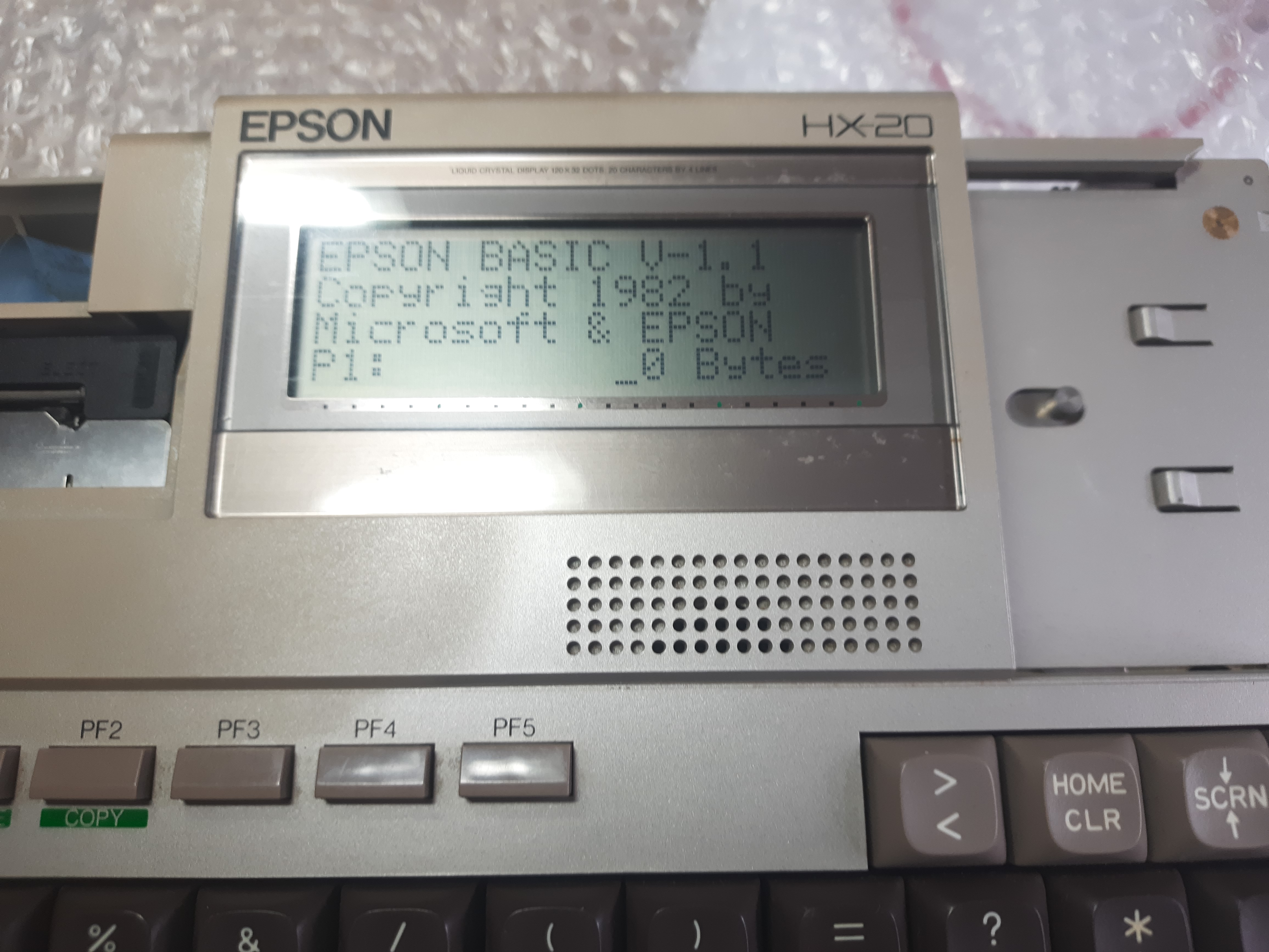
Update: I’ve got a replacement LCD PCD from ebay seller, which works well.
Printer
There is a cool mini printer inside the HX-20. Paper that fits at least in width is still easy available (57mm width). Usually, these paper roles are too fat to fit into the HX-20 compartment intended for them. But it’s possible to wind up the roles until they fit into the roll compartment.
Ink tape also can be bought today, it is called Epson ERC-09.
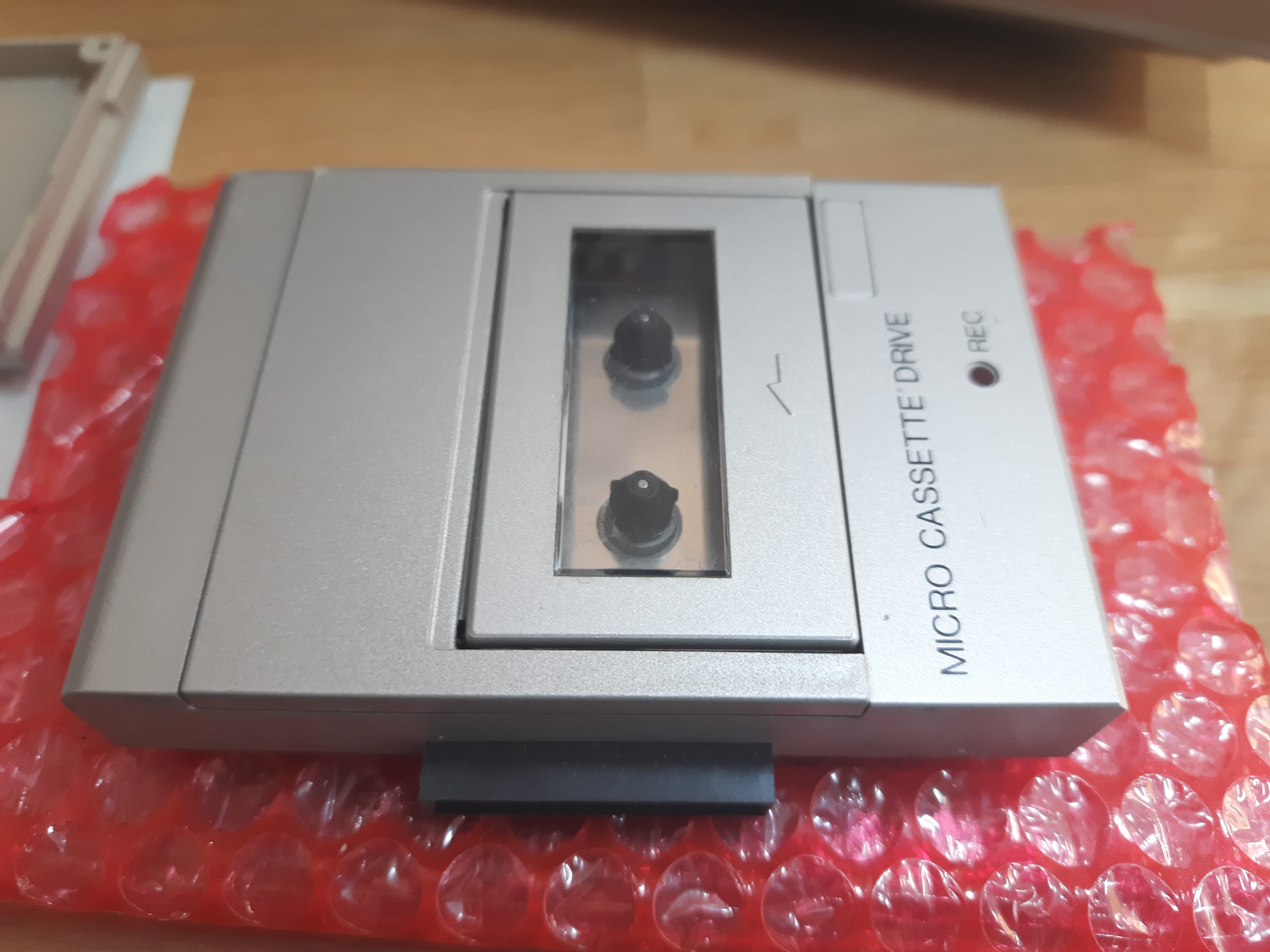
Cassette check and repair
On my first HX-20, the cassette drive works well as it is. Later I bought a second HX-20. There, the cassette drive did not work. So I checked that drive.
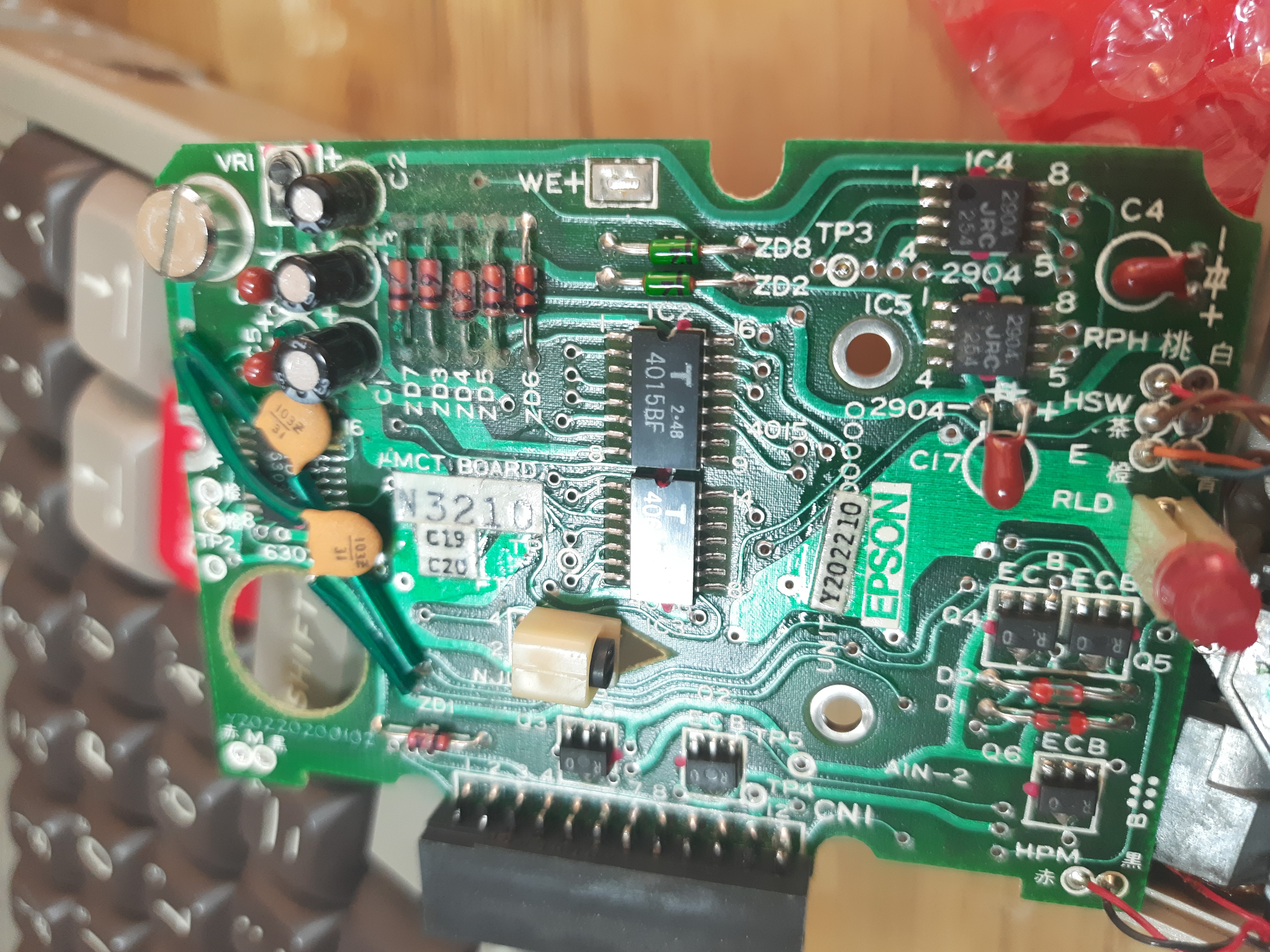
Cassette drive PCB. 2 screws and a soldier point need to be removed/opened to
flip that PCD to the side. Also motor and tachometer connections (4 wires)
need to be desoldered.
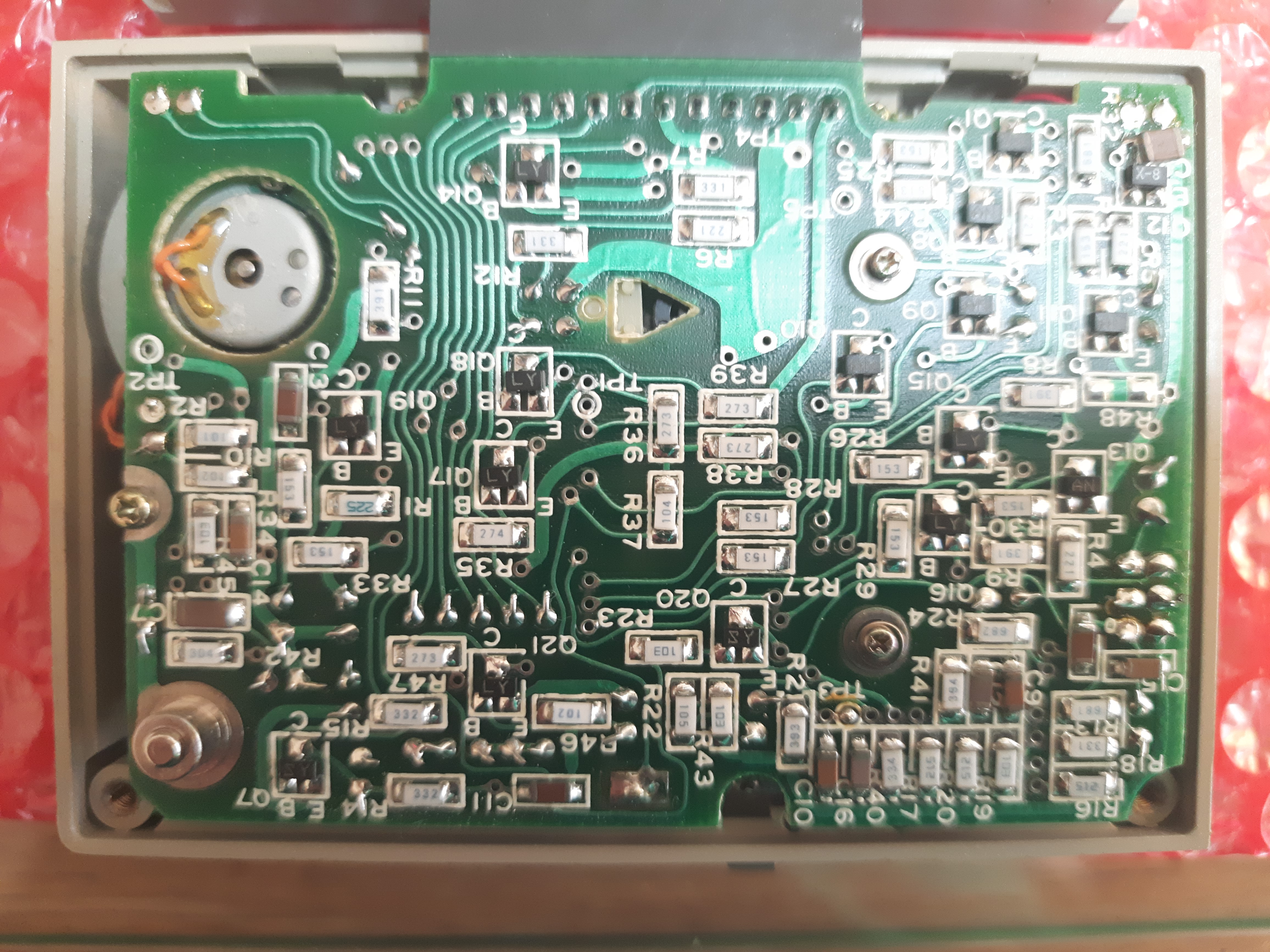
Inner side of PCB. 5 ICs, a few transistors. The chip at the top (with some
capacitors crossed over it) looks like the motor controller. Two 4015 2x4 bit
shift registers, two NJM2904 Op-Amps (bottom right). The white thing left above
of the left 4015 IC is a photo sensor NJL5146, creating pulses for the
tape counter. It takes the pulses from the silver/black roll described below.
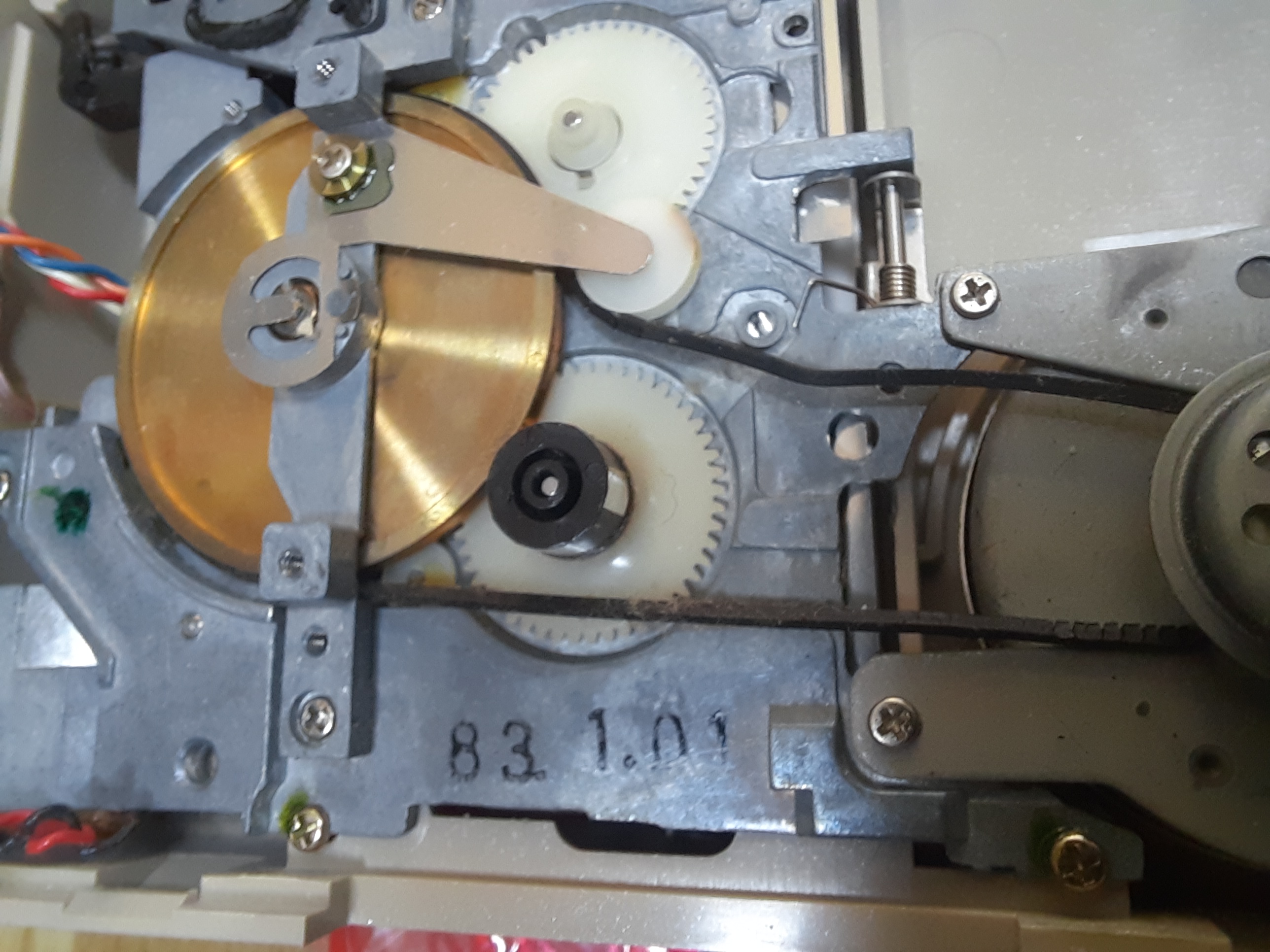
PCB fliped aside. We can see the outweared belt. Motor works, but cannot transmit
any power to the belt.
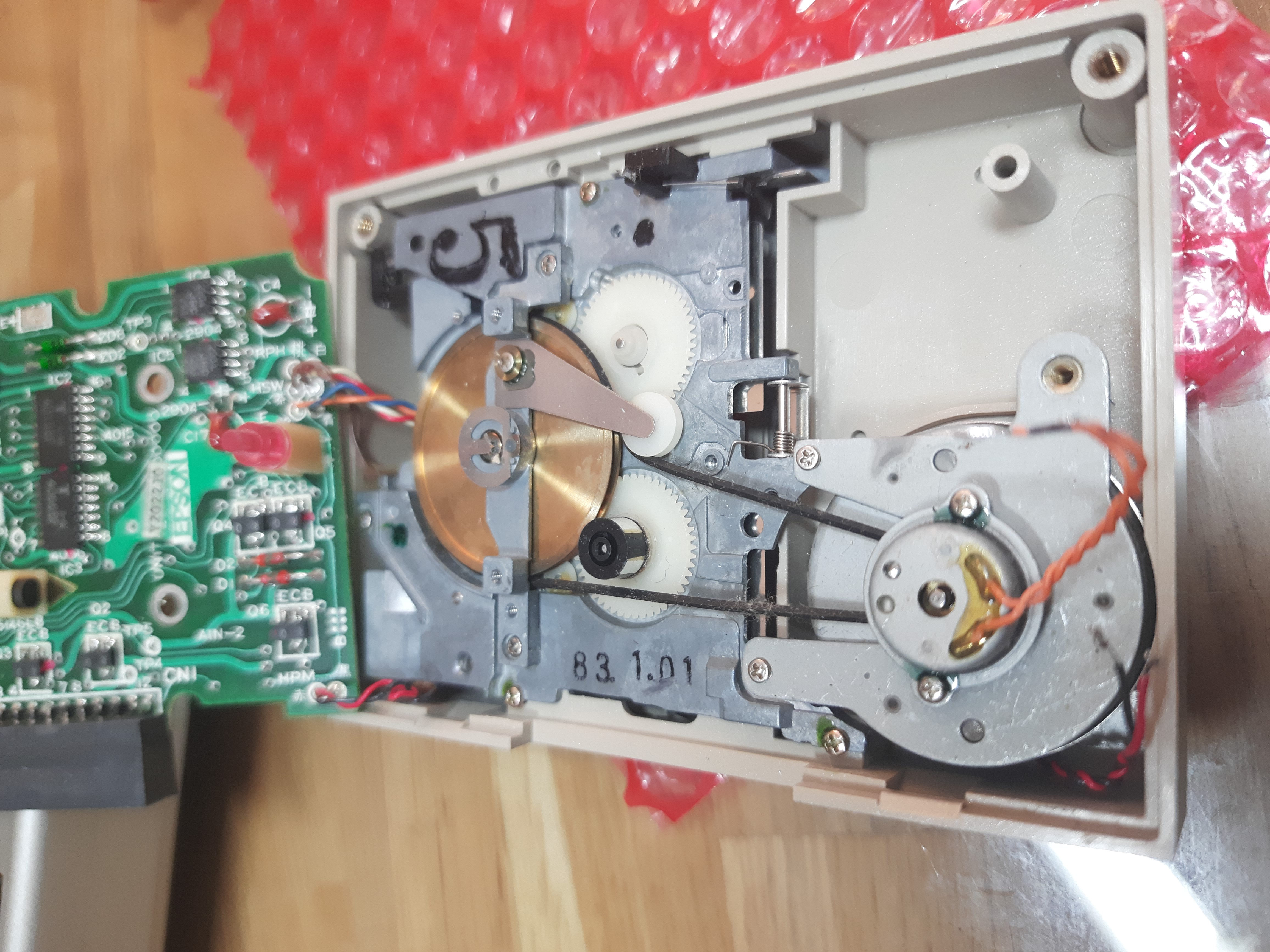
Interesting detail is the black/silver roll on top of the white gear. The four
silver plates give a pulse to a photo sensor on the PCB (see images above),
this is used to implement a tape counter in software. That tape counter gives
values between in range +-32768, 4 pulses per wheel rotation.
Details of old belt. Due to aging, it has many scratches and is too long as a
result:
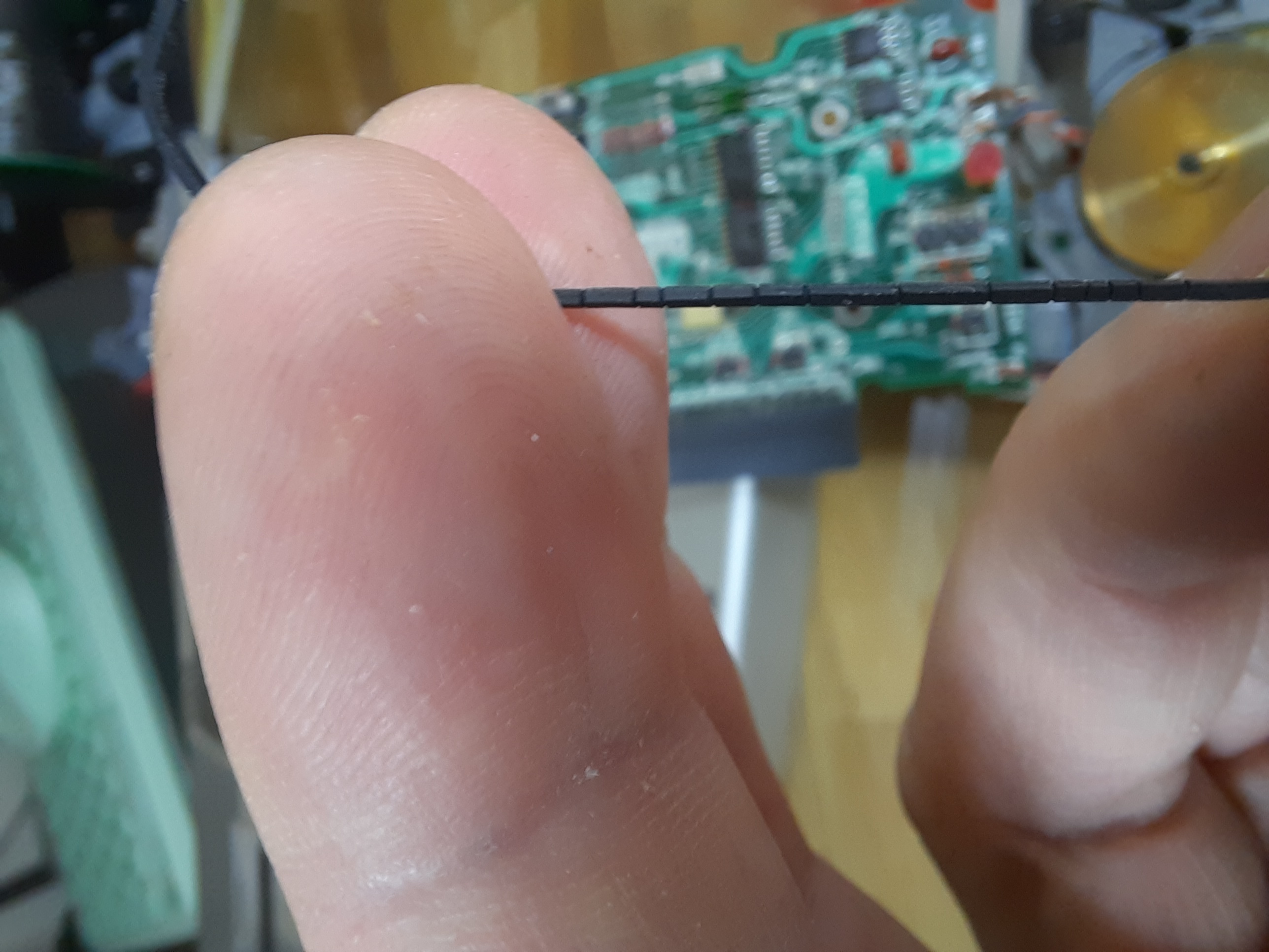
It is possible to replace the belt with some arbitrary rubber belt from the kitchen, but it is known that this will not last very long. So I’ve ordered a set of legit cassette player belts to get a long lasting one. This will last some days.