Battery replacement with 18650 LiIon cells
I wanted to replace a 4x1,5 volts baby cells power arrangement in an old radio ITT teddy 4.
New battery should be the ubiquitous 18650 cell. It offers about 4.2 volts, so I looked for a solution that does up conversion to about 6 volts, and that offers a USB connector to load the cell.
Best would be to have also some battery protection (undervoltage protection, current overload protection).
I found two interesting modules for further analysis. These are discussed below.
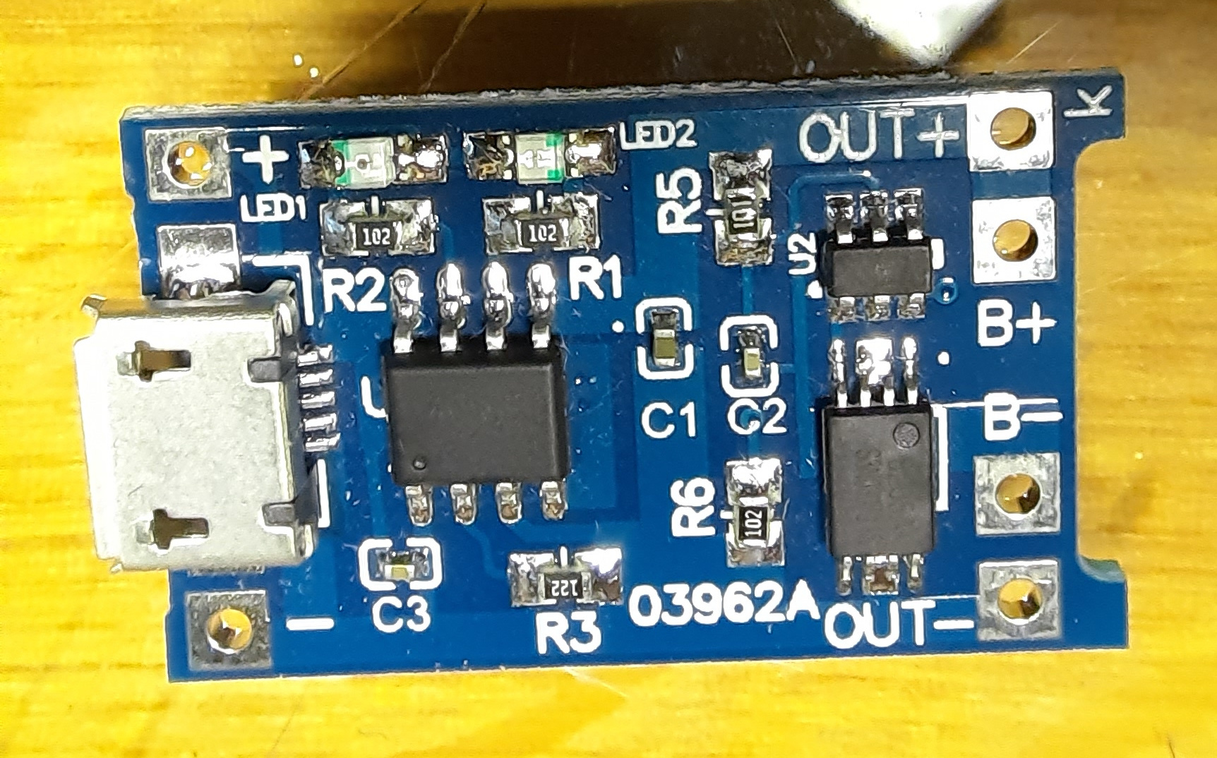
Charging module with TP4056
LiIon charging module. Overcharging and undervoltage protection. Output voltage cannot be higher than battery voltage, no step up conversion.
But I found that the radio still works with about 4 volts.
TP4056 charger chip. DW01A battery protection chip and 8205A MOSFET. MOSFET switches off battery if battery voltage goes below 2.9 volts.
LEDs: red : charging, green: charged.
My findings:
- R3, connected to pin 2, regulates charge current, its value on PCB is 1K2, so 1000mA charge current.
- LED1 goes to pin 7, so this is charge/input voltage detection LED.
- LED2 goes to pin 6, so this is standby/charged LED.
- Pin 4 goes to + (input)
- Pin 5 (BAT) goes to OUT+ and B+
- Pin 3 (GND) goes to - (input), OUT- and via DW01A to B-
- Pin 8 (CE) is supposed to be connected with pin 4 (from datasheet)
- Pin 1, a TEMP sense input, is supposed to be connected to - (from datasheet)
When there is no load on OUT pins, the module takes only about 27µA or less. This means it would be possible to keep the module always connected to a battery, without a switch between battery and module.
More on TP4056 and the module
- Info on TP4056 module
- https://makerbazar.in/products/tp4056-1a-li-ion-lithium-battery-charging-module
- TP4056 datasheet
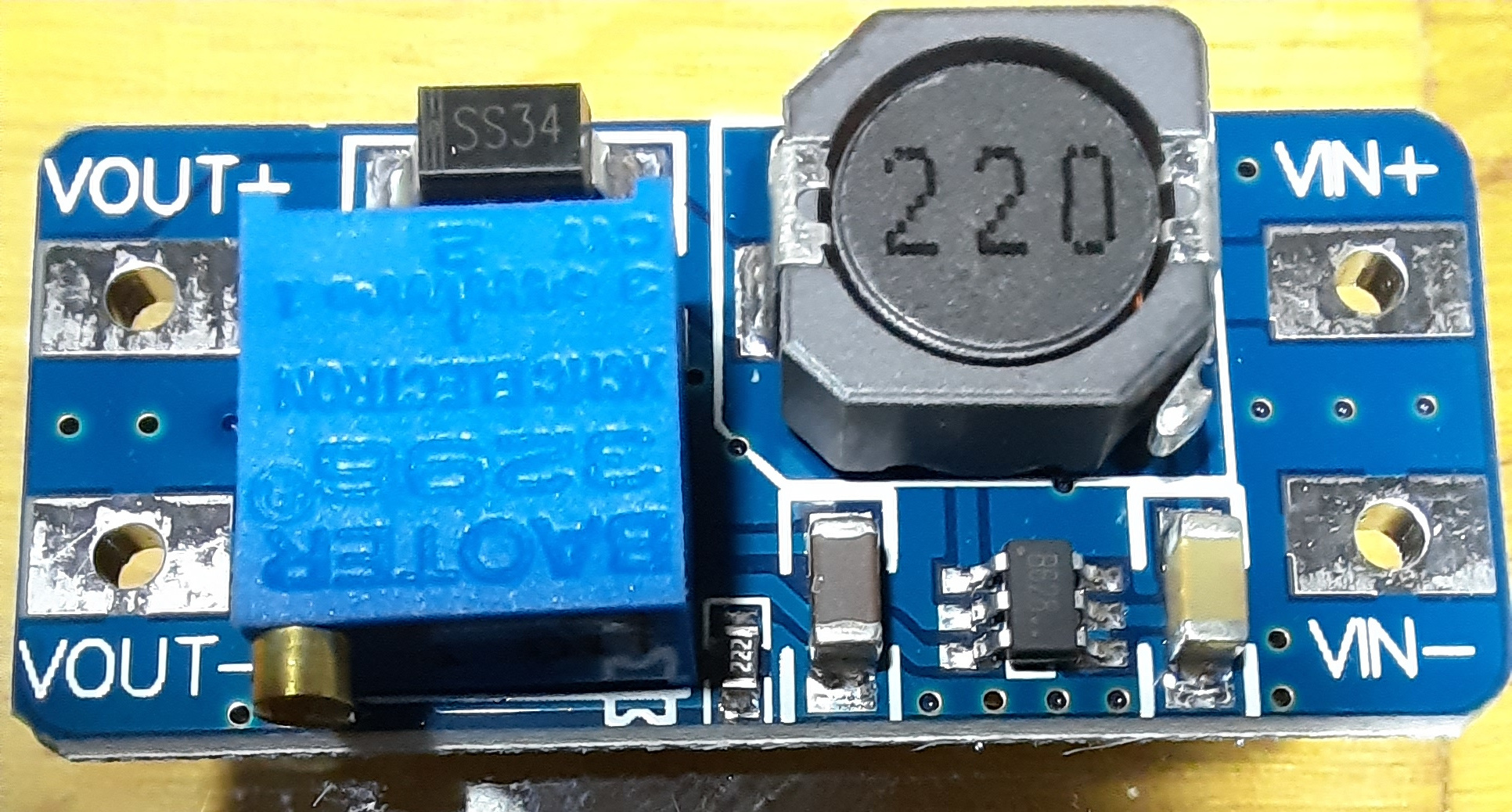
Step up converter module with MT3608
2-24 volts input, 3-28 volts output.
Chip used is a MT3608, 6 pins.
More on MT3608 and the module
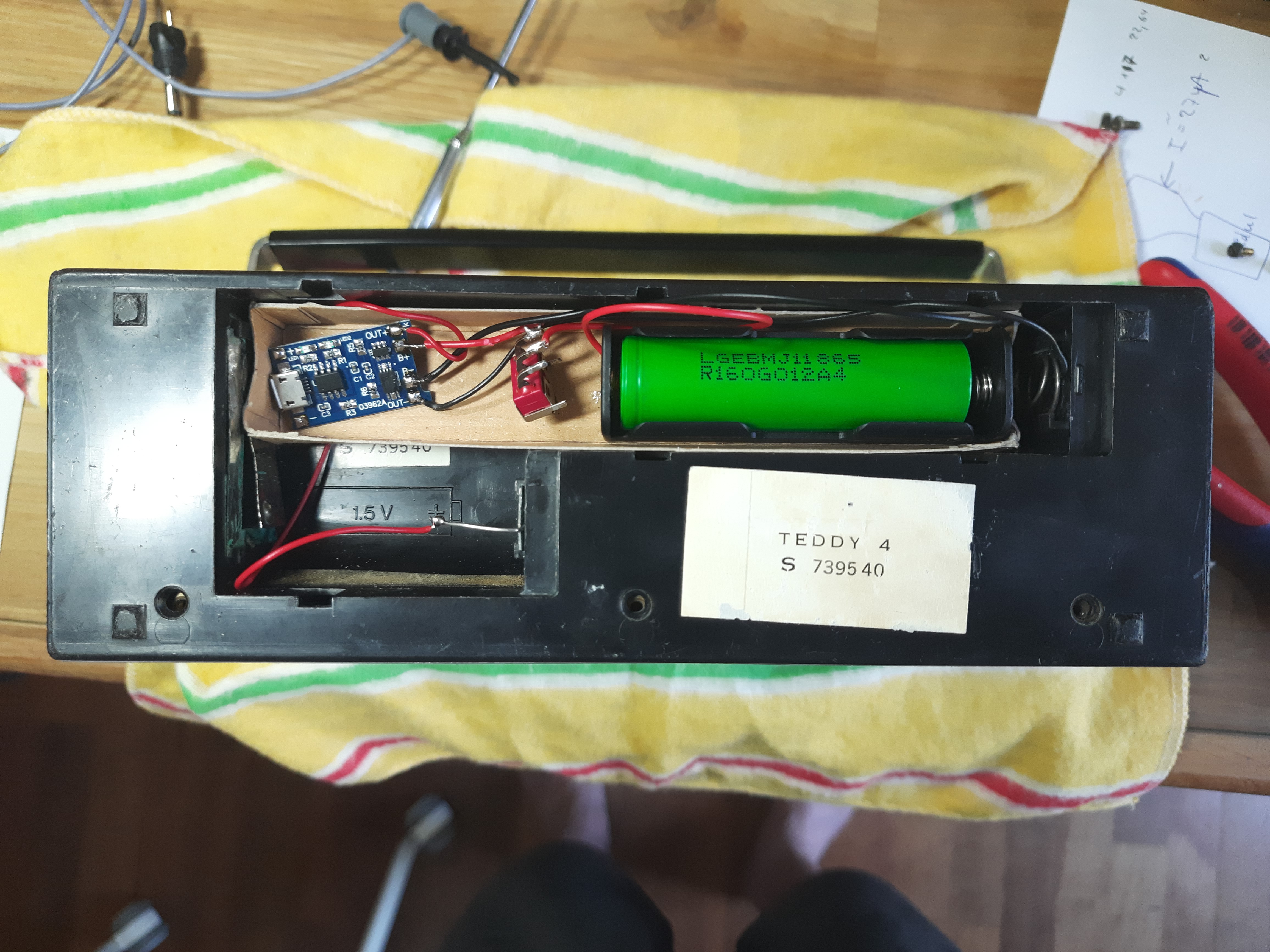
Doing it
The following image shows my solution. A small selfmade paperbox, for isolation purpose, contains the cell with its bracket and the module. The output of the module is directly connected to +/- of the battery compartment of the radio.
There is also a switch visible, between module and battery. But I found that the module can always be switched on, because if the radio is switched off, the module itself takes about 27µA current. This means the battery will work for months. So the switch is not needed, and not used. But it is still soldered in, coming from my experiments.
For loading the battery, I have to open the battery compartment and connect a micro USB cable. But I suppose this is about every month or two months, so no issue with that.