
PDP 11 parts
I own some old PDP11 parts. I try to complete these to have a minimal set of cards to boot the PDP11. This is seen as a long term task and may last several years…
Activity was started in February 2017. In January 2021, I have spent 91+161+3*90 = 522€ on that madness, without any results so far :-) .
In 2022, I could buy a basic PDP unit, without case and in bad condition. This thing is described here
My try to rebuild a minimal system from these boards is described here
Cards described in this document:
- H9278-A backplane
- M8186 CPU board
- M7270 CPU Board
- M8028 DLV-11F serial board
- M3104 serial board
- M8067 512KB RAM
- M8044 32K RAM
- EMULEX CS02H1 serial controller.
PDP11 CPU Board - M8186
Bought February, 2017, got it from UK, payed 83 british pounds (~91€)
KDF-11-AA 5013326C
More info on this board is here: http://web.frainresearch.org:8080/projects/pdp-11/dcf11.php
A citation
from http://web.frainresearch.org:8080:
Either processor would be desirable to own, but the M8189 provides more value.
An M8186 would require additional modules with serial ports, boot ROMs and
potentially an LTC register to provide a complete system. This could be
accomplished by pairing it with a multifunction board, but it would still take
up as much or more space as the M8189. In small form factor systems, with
a H9281 backplane, the M8186 would be the only choice.
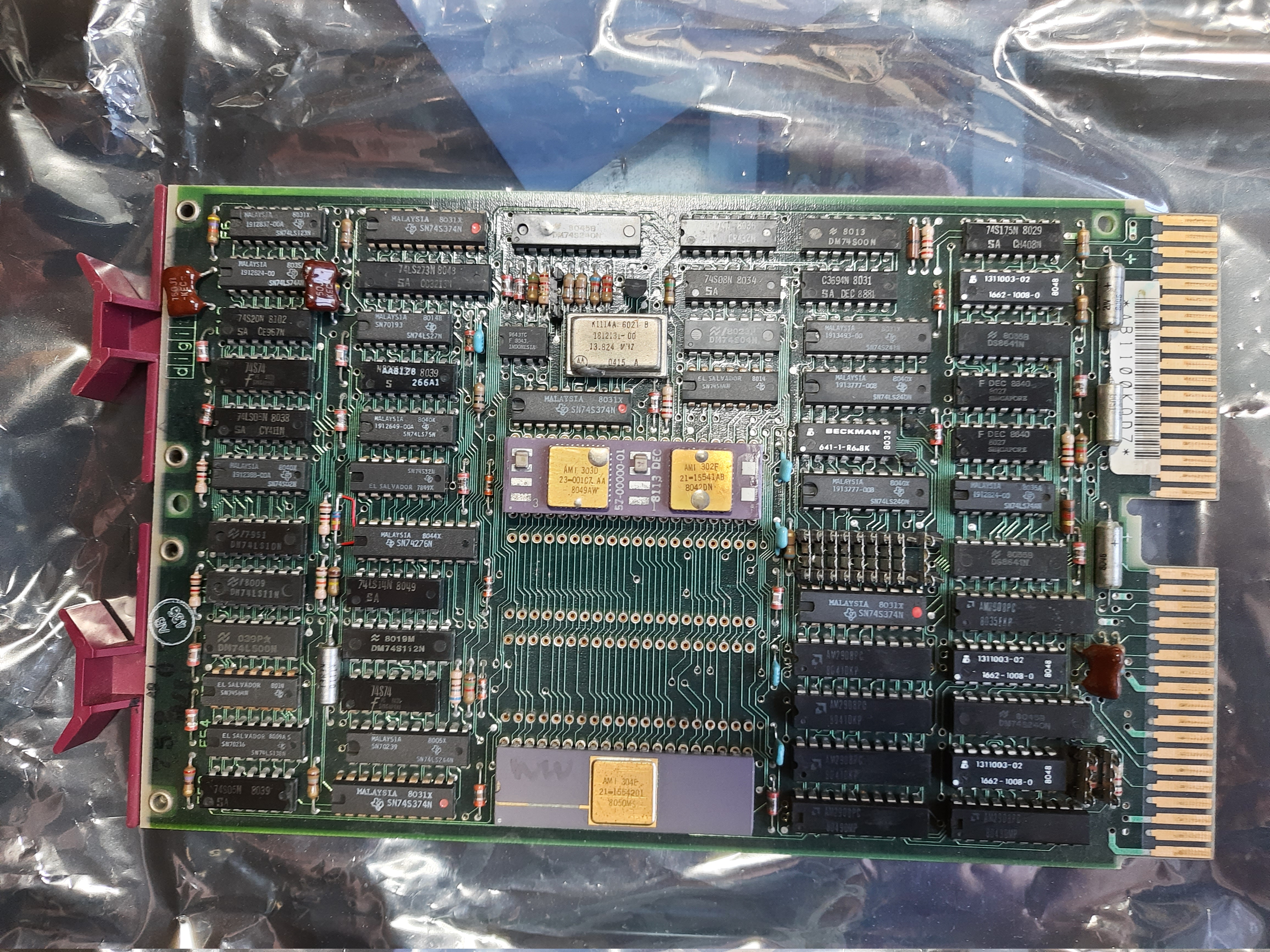
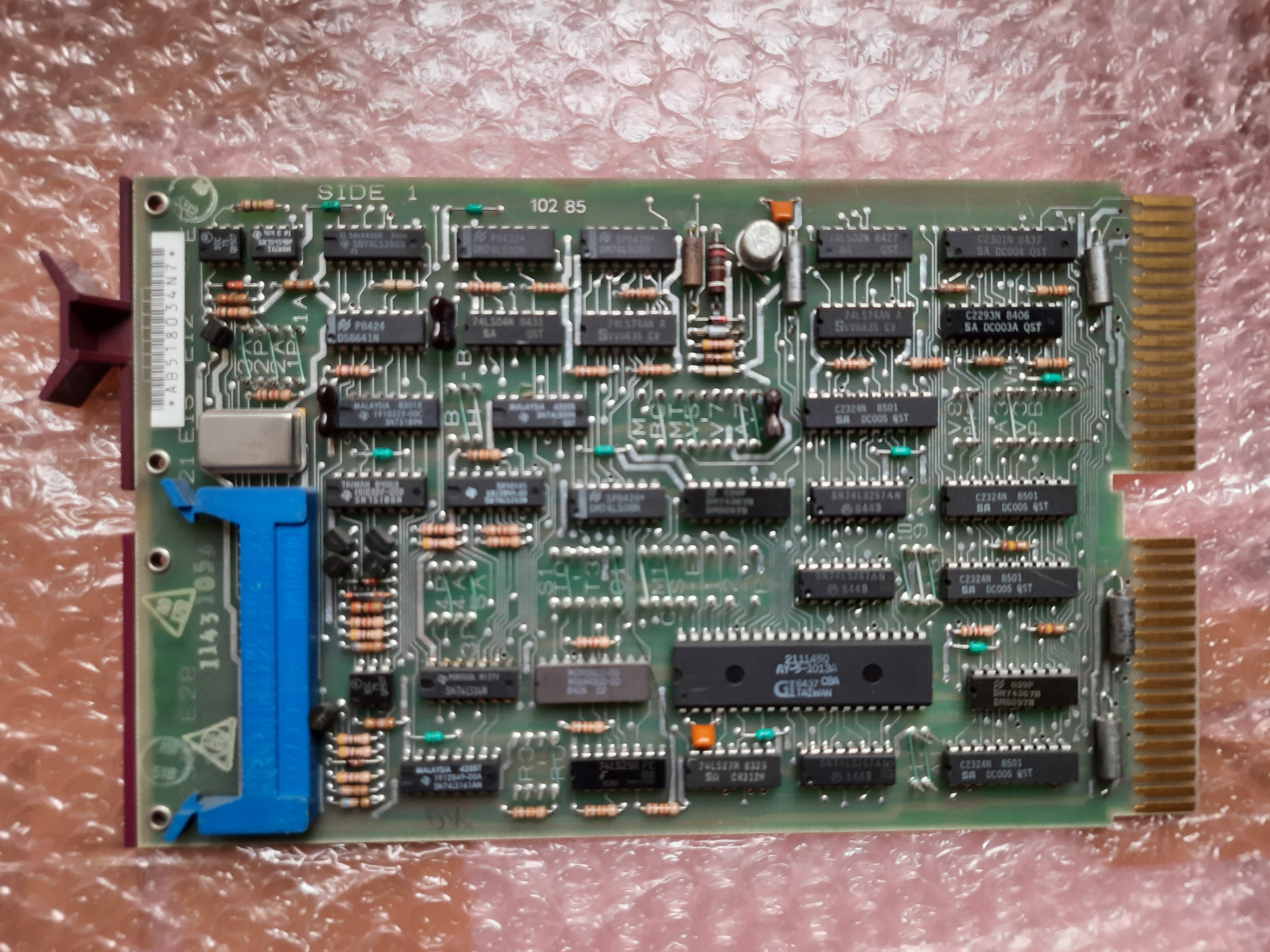
Above is the M8186 board with CPU in the middle and the MME at the bottom.
This is a CPU-Board, as far as I know from a DEC PDP 11/23.
Citing from http://web.frainresearch.org:8080/: The DCF11-based processor is a microcomputer with a 16-bit address bus and a 16-bit data bus. It was used in the PDP-11/23 line of Q-bus computers, and the PDP-11/24 line of UNIBUS computers.
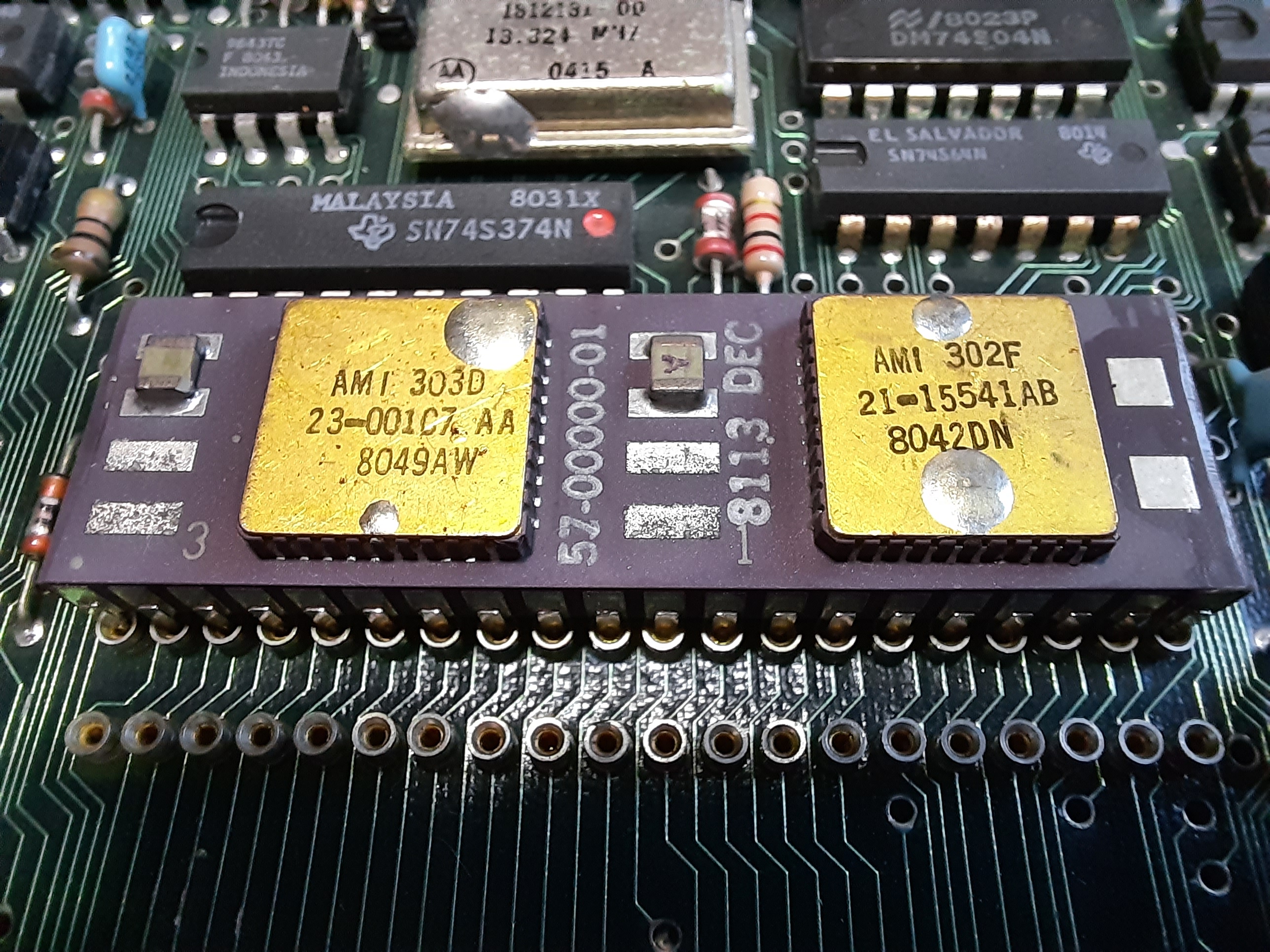
The board contains a KDF11-A CPU, this is the chip with two golden caps. The CPU has date code 81/13, so calendar week 13 1981. Date codes on the two ICs on the CPU are 1980, 49th and 42th calendar week. Board number is KDF-11-AA 5013326C, so it’s a revision C and supports 22-bit addresses.
The CPU hosts two ICs, one is the AMI 303D (23-001C7 AA), the other one is the AMI 302F (21-15541 AB). From Internet, I learned that 303D is the Control Chip, and 302F is the Data Chip. The CPU, code name ‘Fonz’ runs at 3.6 Mhz, Bus has the same frequency, it has in sum 29.000 transistors.
The other gold cap chip is the AMI 304E Memory Management Unit (MMU) for PDP-11 computers. Complete name of this chip is KTF11-AA MMU 21-15542-00
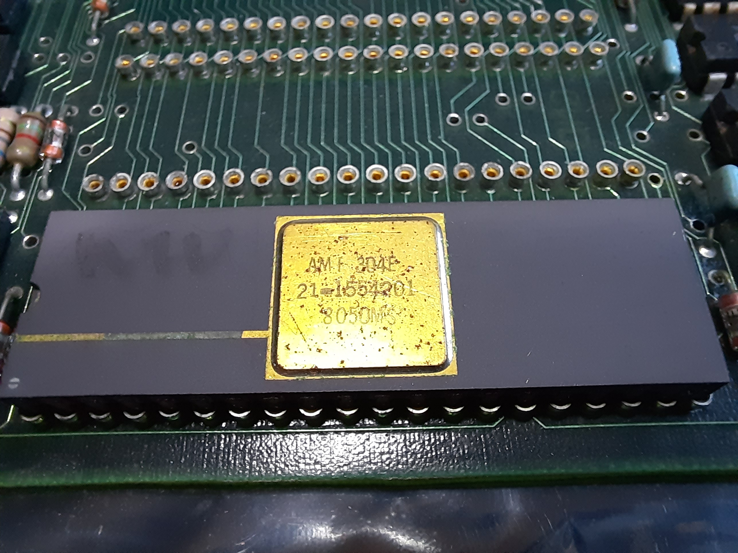
Date code on MMU is 1980, 50th calendar week.
22-bit addressing and the existence of the MMU allows to address more than 65KB, maximum is 4MB RAM.
The Quarz oscillator has 13.824 MHz.
All other chips are more or less standard TTL chips.
On the two free 40 pin slots, an FPU (and maybe other chips) can be inserted.
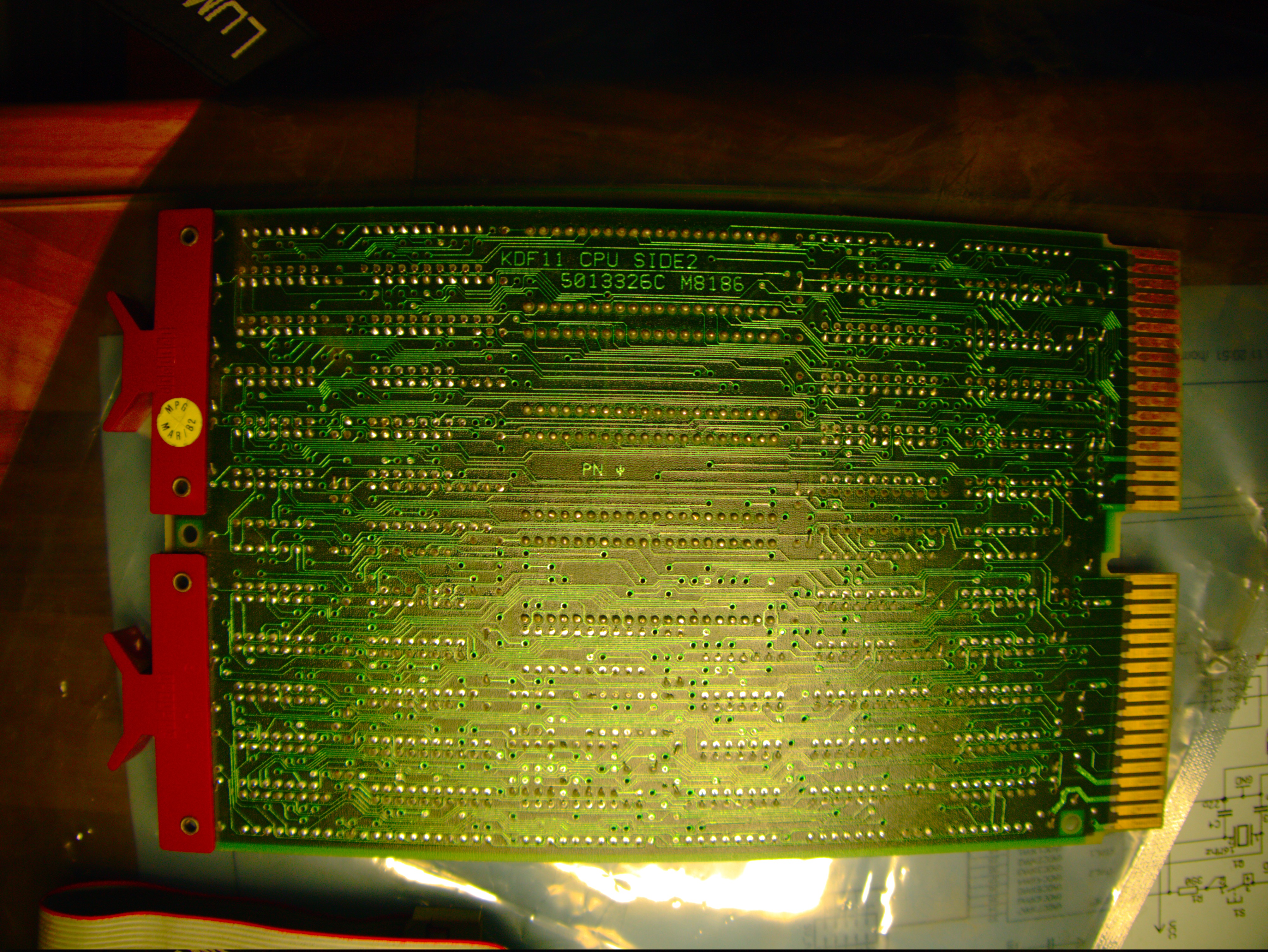
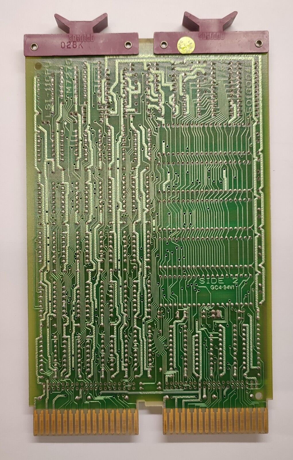
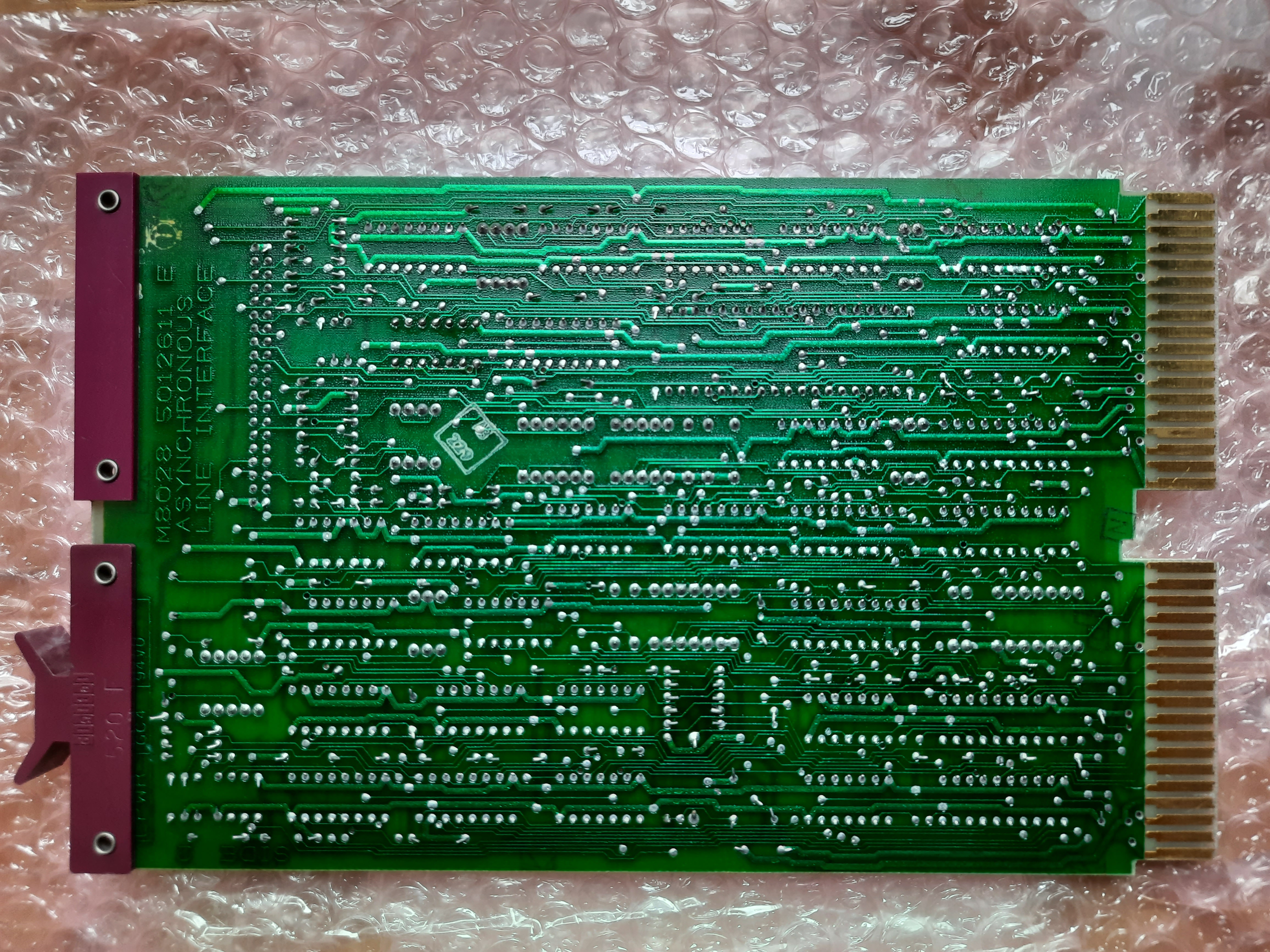
Solder side of M8186 CPU board
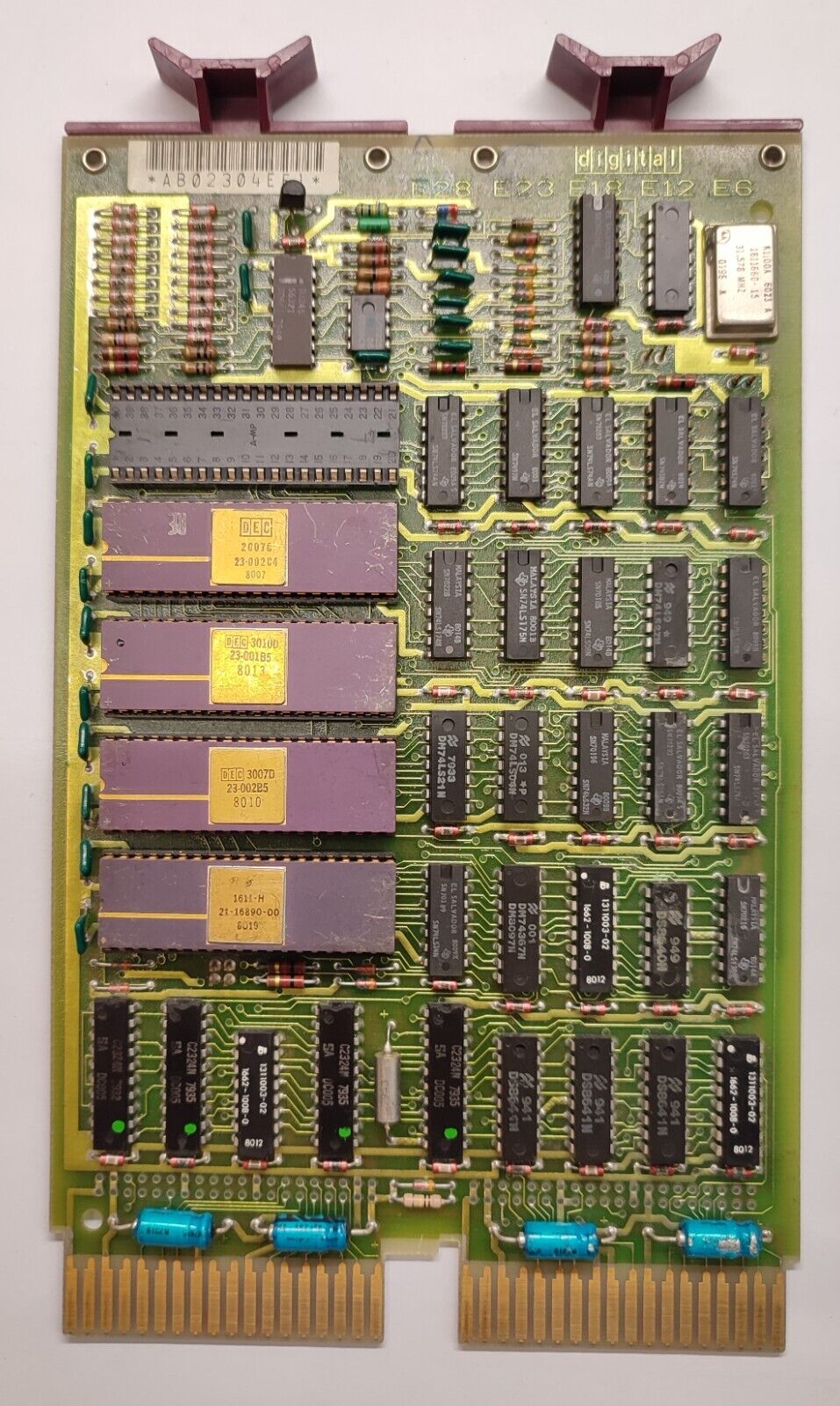
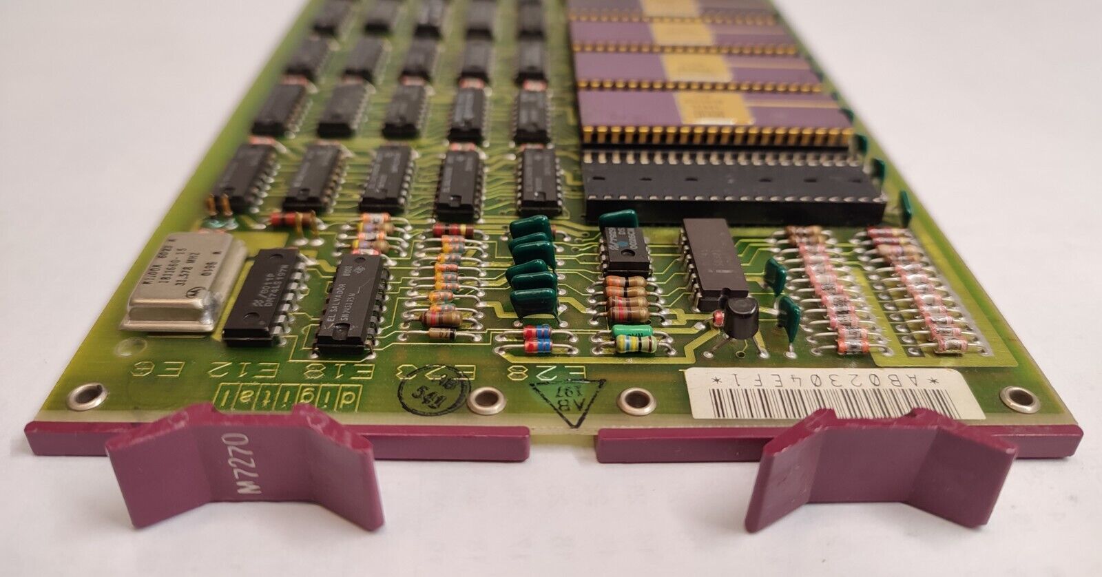
M7270 CPU Board
Sold as “DIGITAL EQUIPMENT DEC M7270 LSI-11/2 KD11-HA CPU QBUS Rarität”.
This is first version of the LSI CPU boards, used in PDP-11/02 systems. The “CPU” is formed from a set of 4-5 chips. These are “Control” and “Data” related chips.
In two of these (3010D and 3007D) the microprogram for the CPU instructions is located. Depending on their versions, the board supports e.g. floating point instructions and other extended features.
Quarz is 31.578 Mhz.
More infos on this board: https://www.cpushack.com/2017/11/22/cpu-of-the-day-dec-lsi-11-chipset/
ebay seller images:
PDP Backplane - H9278-A
QBus 22 Bit Backplane with 8 Quad slots
Bought February, 2017, got it from US of A, 165 US$ (=161€, uh, expensive, how could I)
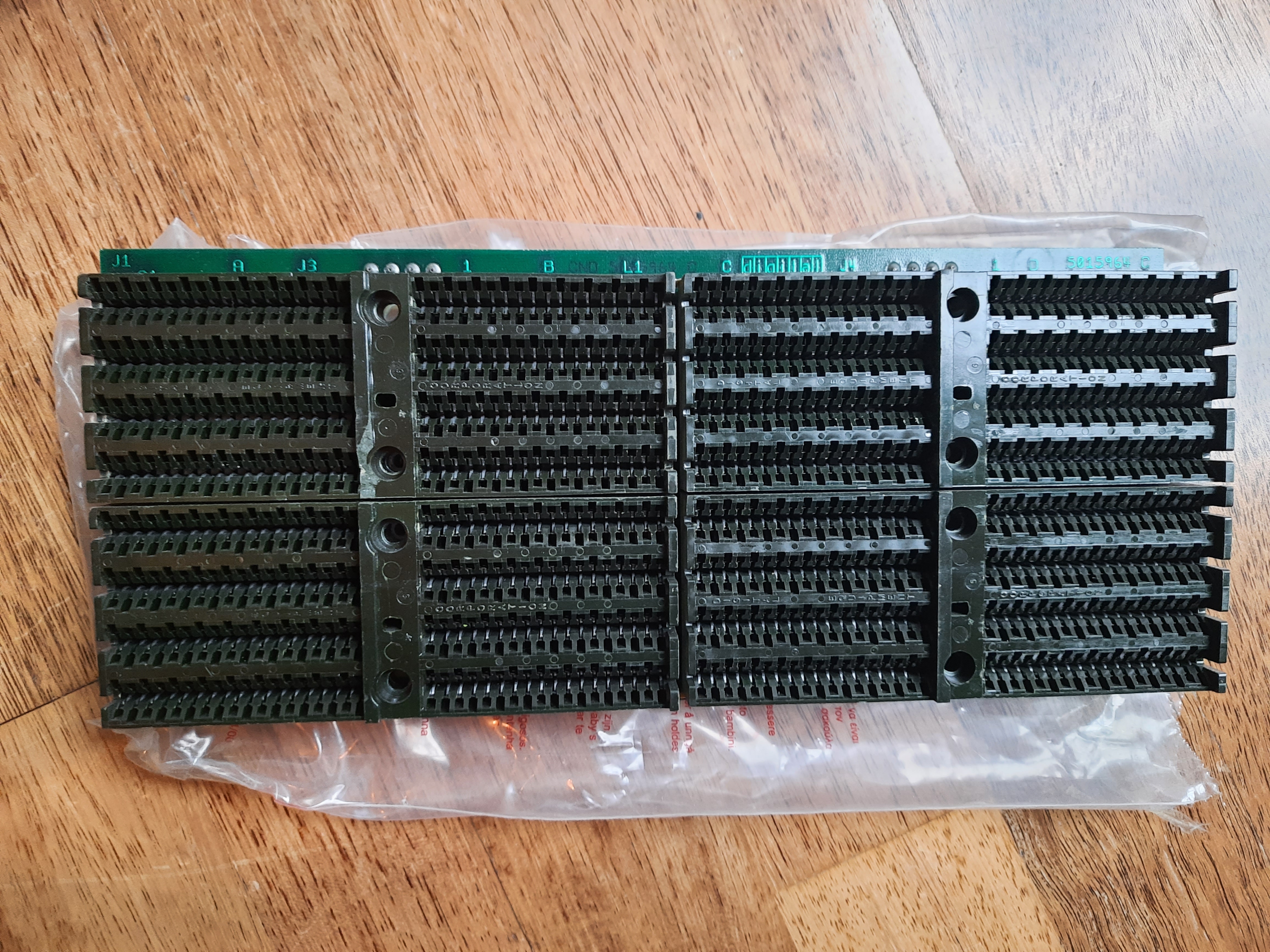
It seems possible to mix dual and quad slot cards in the PDP concept. This backplane allows dual and quad cards, so I am on the happy path here.
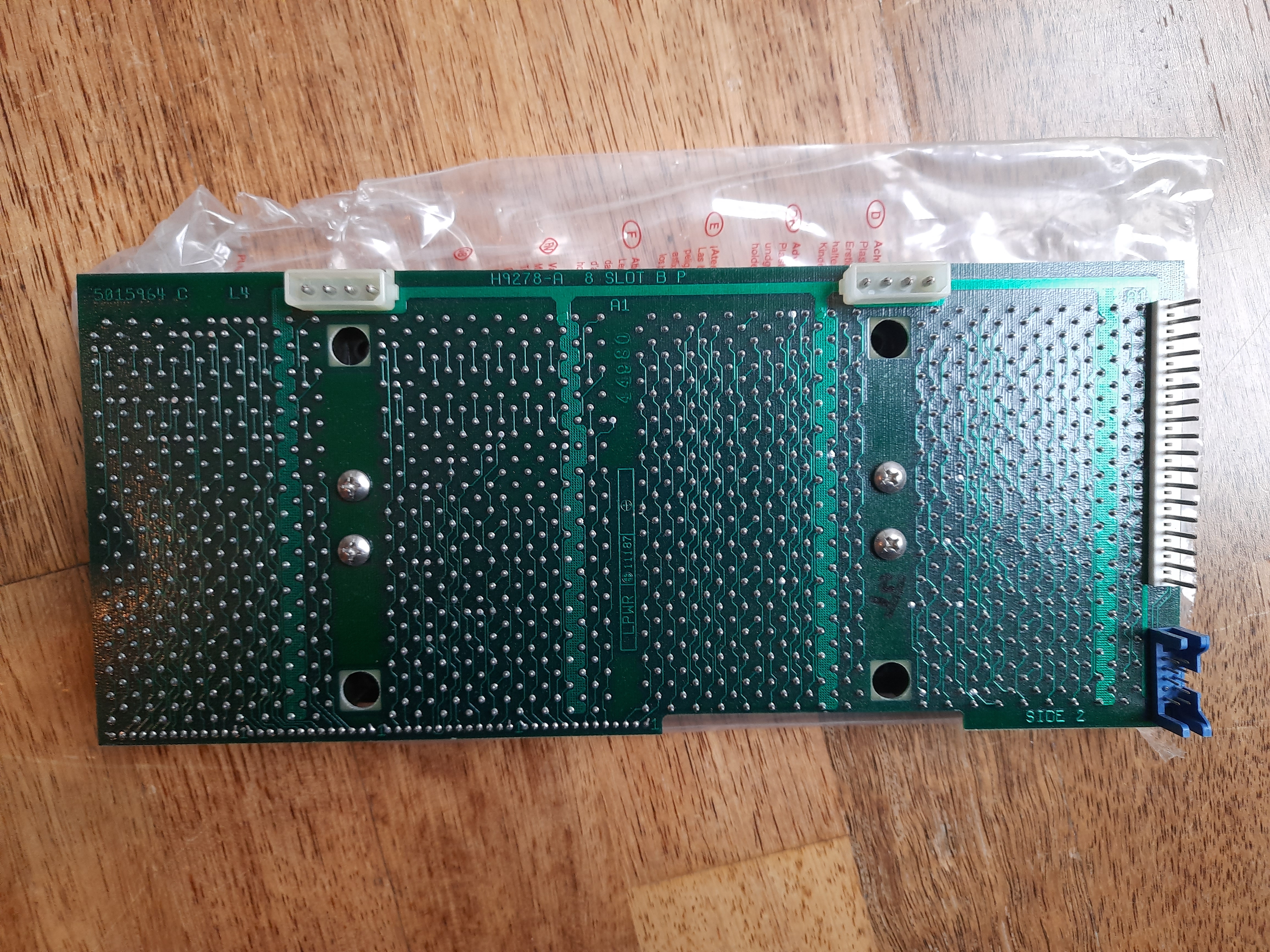 9278 backplane from solder side
The backplane comes with 4 connectors in total. 2 of them look like power connectors (these with 4 pins at the top).
There is an inline connector with 18 pins at the right and a small blue connector with 2x5 pins (9 pins used).
The large inline connector with 18 pins is the main power connector. In systems manual, it is called J1.
The small blue connector is a connector that has some signals coming and going to front panel. In systems manual, it is named J2. Some of the contacts are crucial for booting a PDP11 and need to be served with the correct signals on startup. See e.g. here: http://www.diane-neisius.de/pdp11/#atx .
Serial board DEC M8028 DLV-11F
The DEC M8028 module is a Serial Line Unit (SLU). It is a dual sized board, has 18 bit address bus and offers a single serial port. It is console compatible, i.e. can be used as a system console. Maximum baud rate is 19200 baud.
Bought January 2021, from Germany, payed 90€. I bought three modules at once ( M8028, M3104, M8067 for all together 270€).
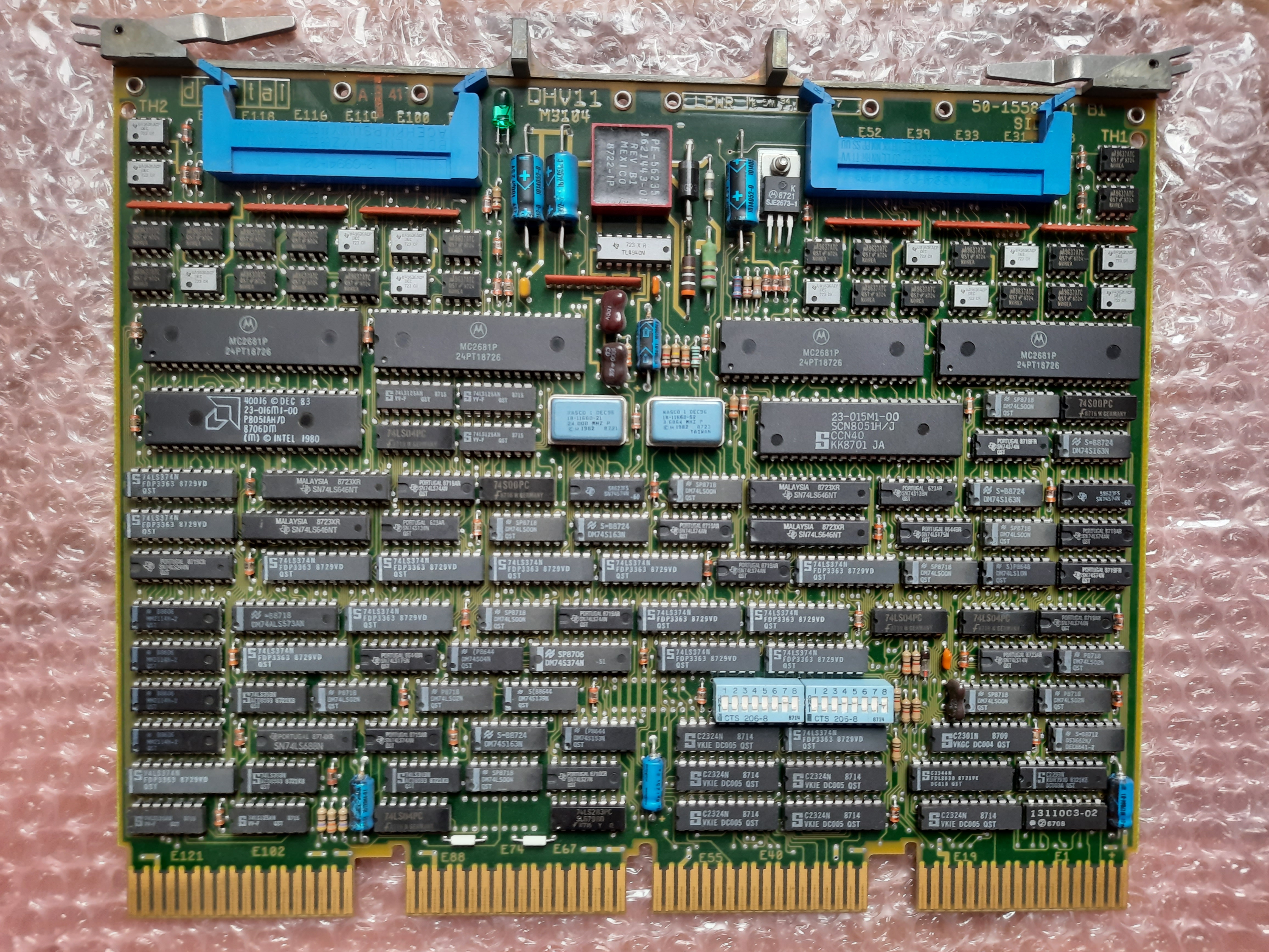
Serial board DEC M3104 - 8 Line serial port
The DEC M3104 module is a serial port multiplexer module. It is a quad sized board, has 22 bit address bus and offers 8 serial ports. Maximum baud rate is 38.400. It uses up to 4.25 ampere at 5 Volts, so it is a quite power-hungry module.
Bought January 2021, from Germany, payed 90€
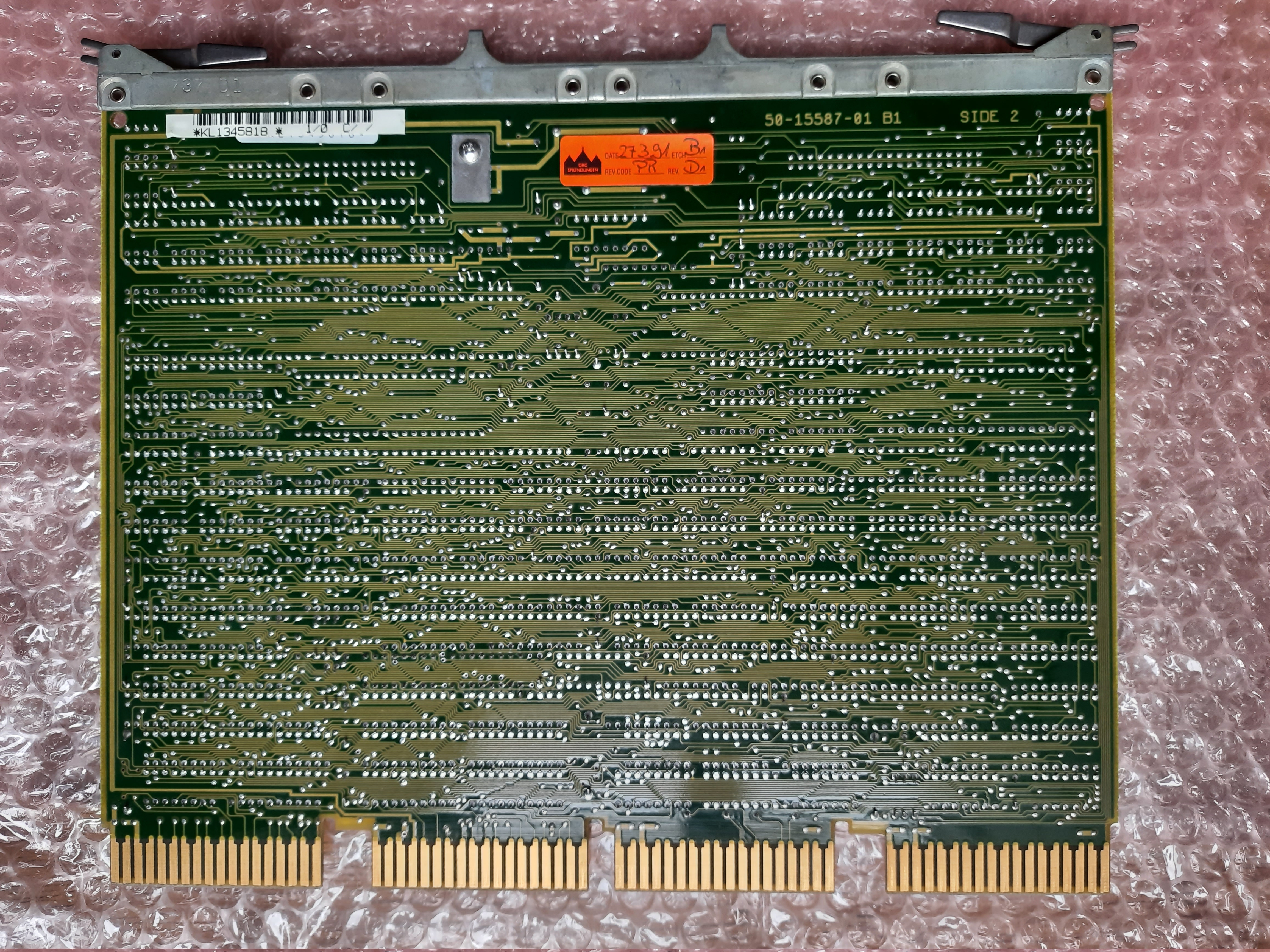
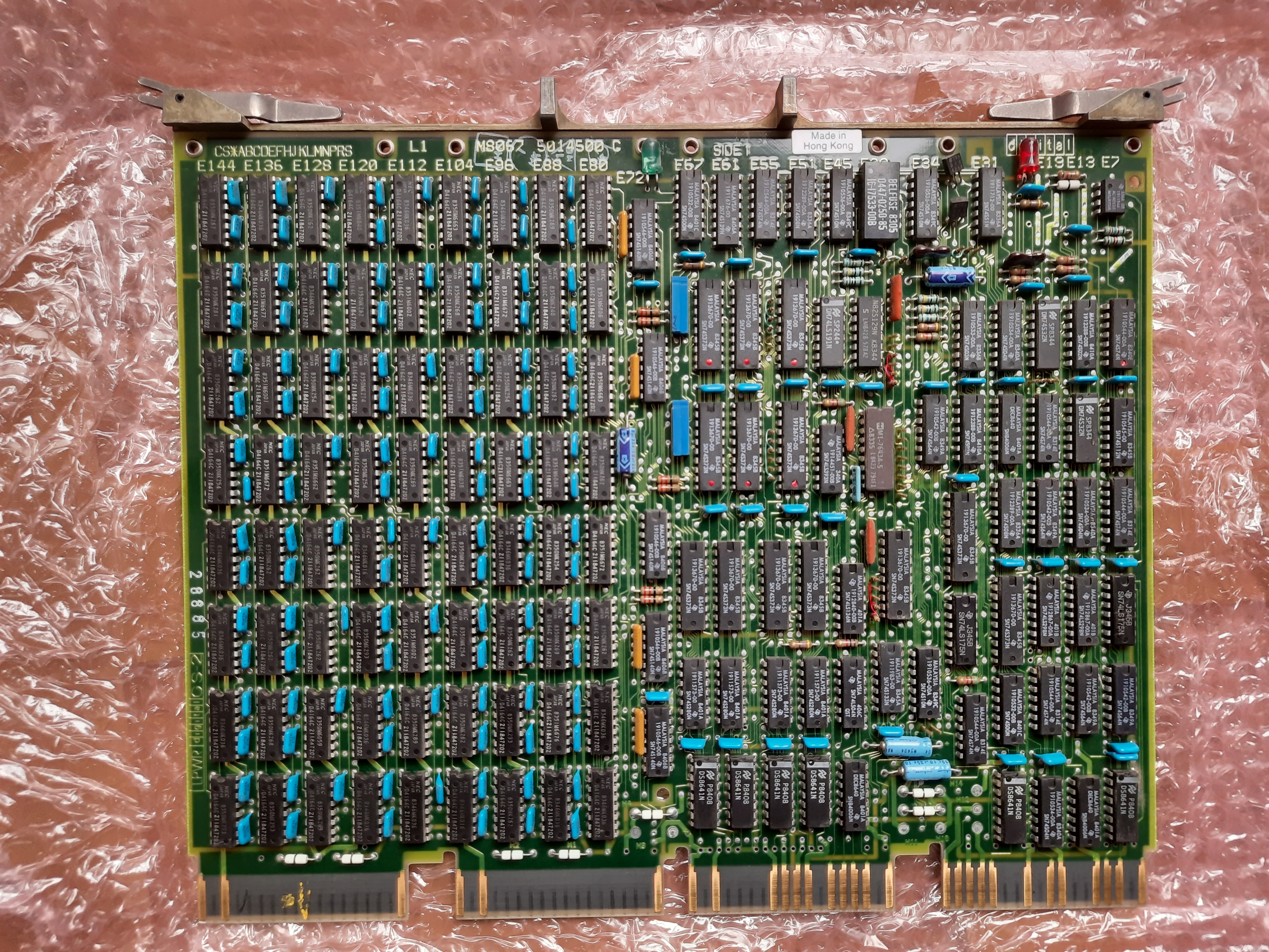
Memory Board DEC M8067 - 512 KB RAM
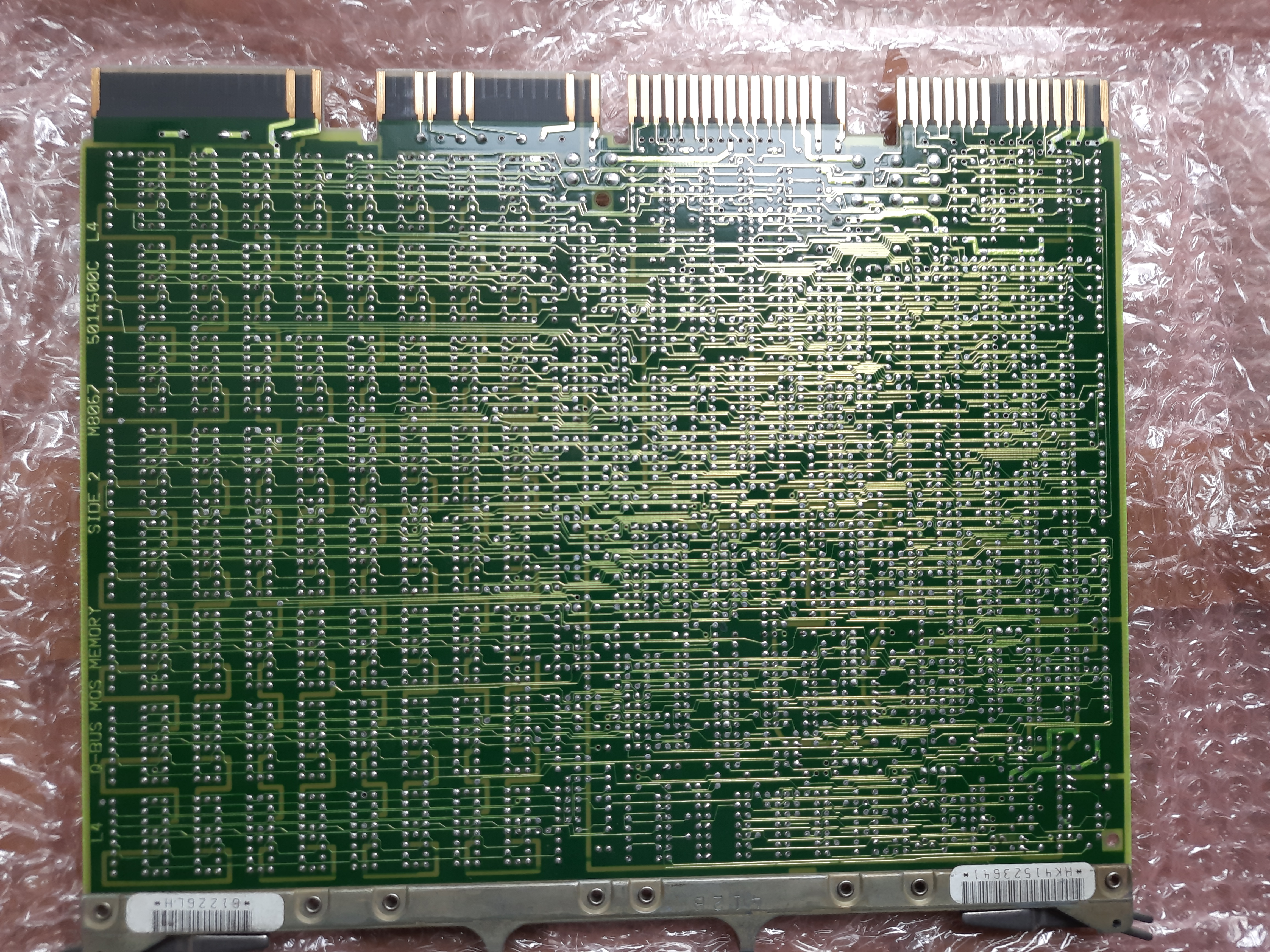
The DEC M8067 is a 512KB RAM module. It is a quad size board, requires 22 bit address bus. Data width is 18 bits.
Bought January 2021, from Germany, payed 90€
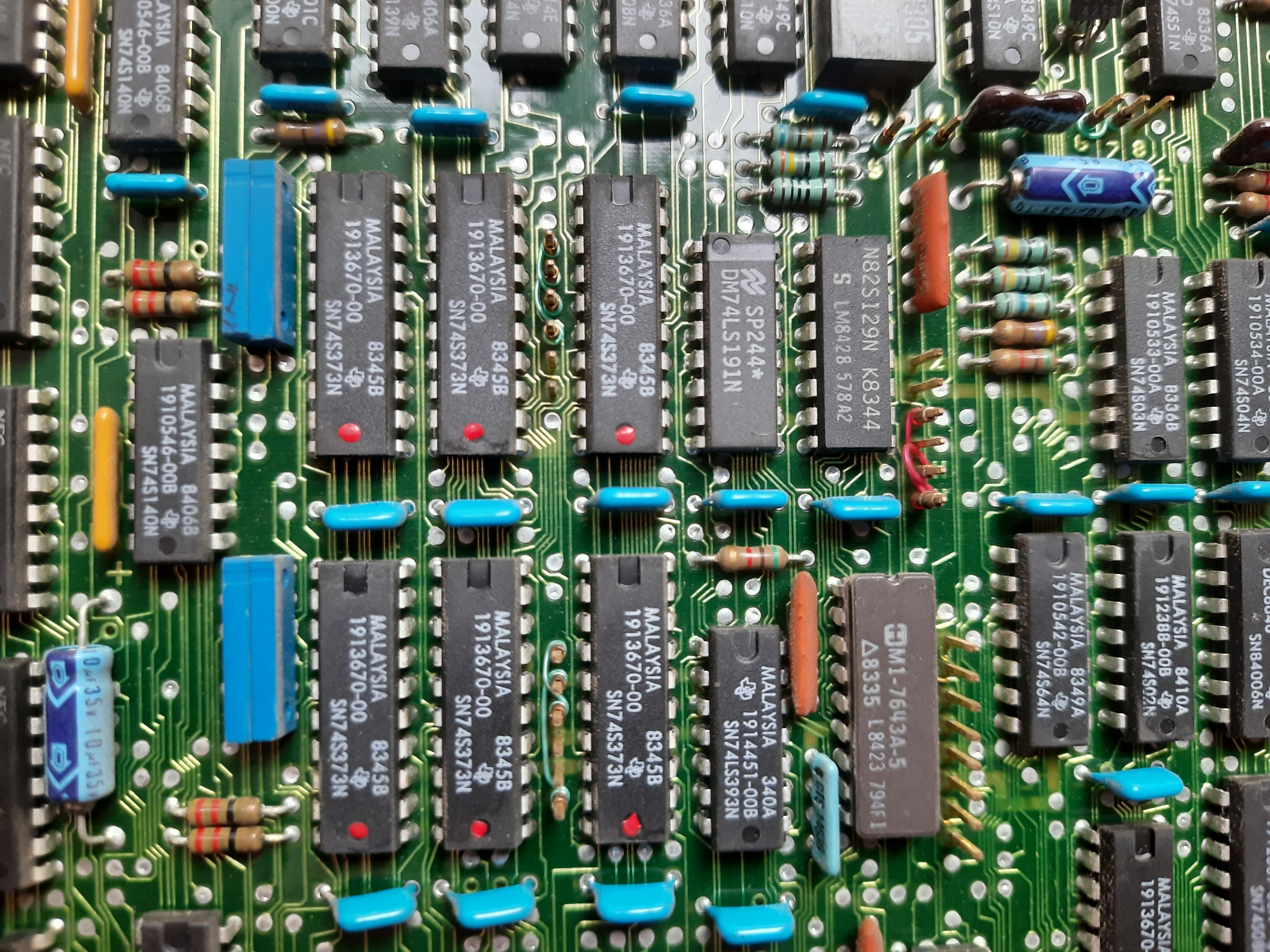 Close look …
Another M8044 RAM
M8044-BC with 32 K Words RAM.
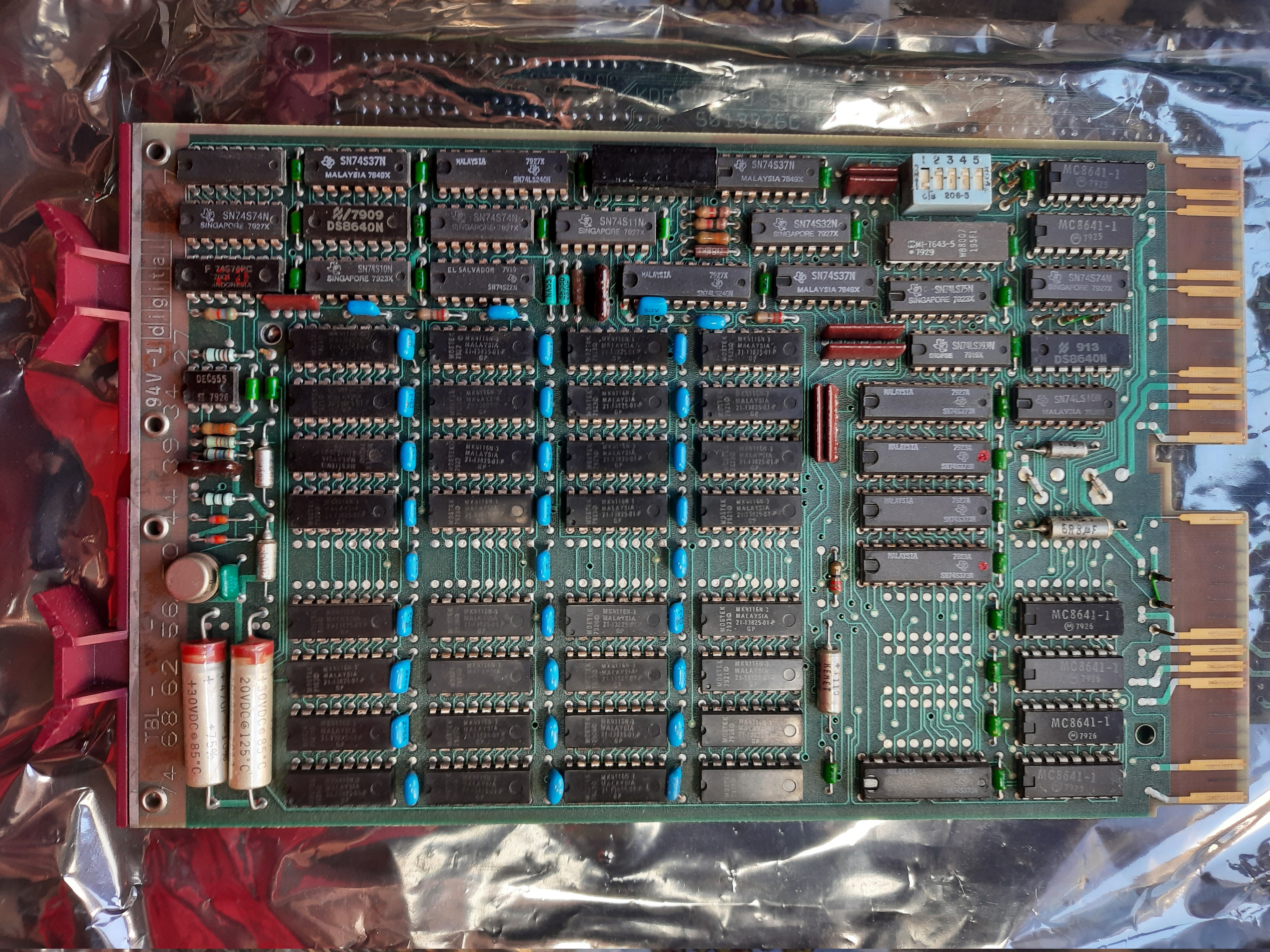
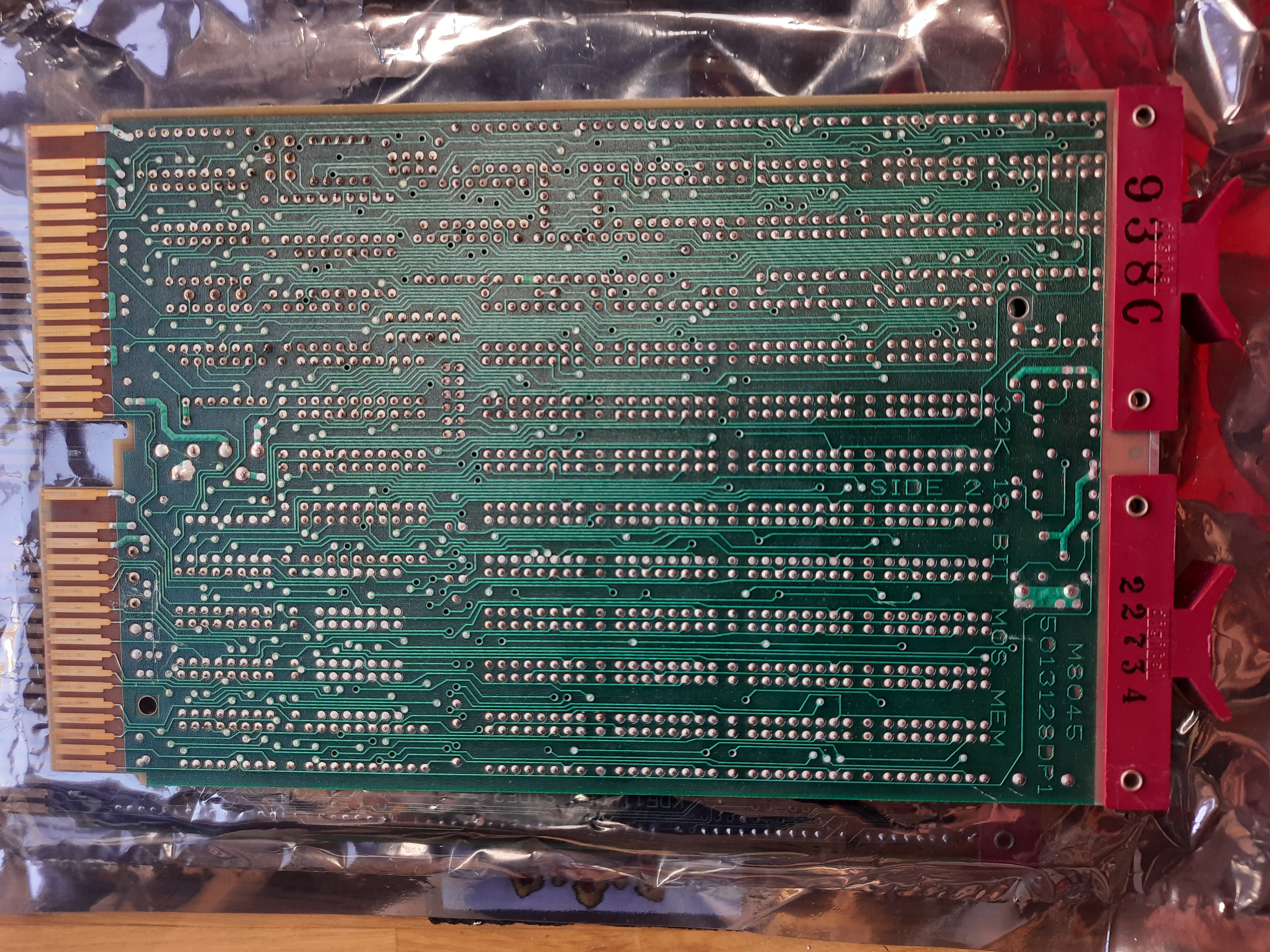
Mostek MK 4116-N3 RAM Chips. This has 16Kx1Bit. There are two areas with 4x4=16 chips on the board, so in total 32 chips.
16Kx32 = 32Kx16 = 64Kx8.
So it is a board with 64 KBytes, but organized in 16-bit words. This means the board has 32K words.
EMULEX CS02H1 Controller.
This was sold to me as CU0210702 Controller. On one of the chips there is a label CS0210202-H1L. So it seems to be a CS02H1 Controller.
“DH-11/DM-11 or DVH11 compatible”, QBus, 22 bits.
The CS02/H provides 16(!) asynchronous communication channels. It either emulates a DEC DH11 with AM11 modem control, or two DEC DHV11s.
So this is a board that supports up to 16 terminals. Wow. And not needed in configurations I can think of.
Next steps to do
I plan to set up a minimal system to allow booting the CPU. For that, I want follow these steps
- Buy a serial card to connect my PC via RS232. There are many different of these cards available, I look especially for M8047 (because it also offers RAM and ROM option) and M7195. Done!
- Provide required RAM/ROM, maybe via a simulation with an AVR or whatever. If I can get a M8047, this card could also provide required RAM/ROM. Another option is to buy an additional RAM card. Done!
- Connect everything and boot :-) Done!
Going further
In another document I have described my try to set up a minimal working system from the PDP parts I own.
Further reading
Online Chips museum PDP11 http://silirium.ru/dec-pdp11.html
Frain research on PDP11
https://hackaday.io/project/156536-building-a-pdp-11
Diane Neisius page about setting up a PDP11 from parts
QBUS Front Panel Project
DEC QBus Documents on bitsavers
DEC Forum at Vintage Computer Federation
- https://forum.vcfed.org/index.php?forums/dec/
- RAM Cards Thread https://forum.vcfed.org/index.php?threads/qbus-sram-card-thoughts.1238061/
Cool DEC site, Netherlands https://www.pdp-11.nl/
Gunkies Upgrading Backplanes https://gunkies.org/wiki/Upgrading_QBUS_backplanes
New harddisk for old PDP https://www.5volts.ch/pages/pdp11hack/