DEC Digital OBA11-MF
DEC Digital OBA11-MF bought in poor condition from ebay. It has no case, has some physical damage. Sold of course as defective.
All together this seems to be a kind of “embedded” PDP 11/03 with only a bare minimum of boards and no intention for extending it later on. Maybe used as a control unit in some chemical plant or whatever. here someone has a picture of another device like this.
At some time the CPU was updated to a 11/23 board.
So, I have a 11/03 barebone with a 11/23 CPU board. Nice.
Ebay sellers text:
DEC Digital Model OBA 11-MF mit verschiedenen Steckkarten. M 8045, M 8029, M 8047, M 8186
Cards found in device:
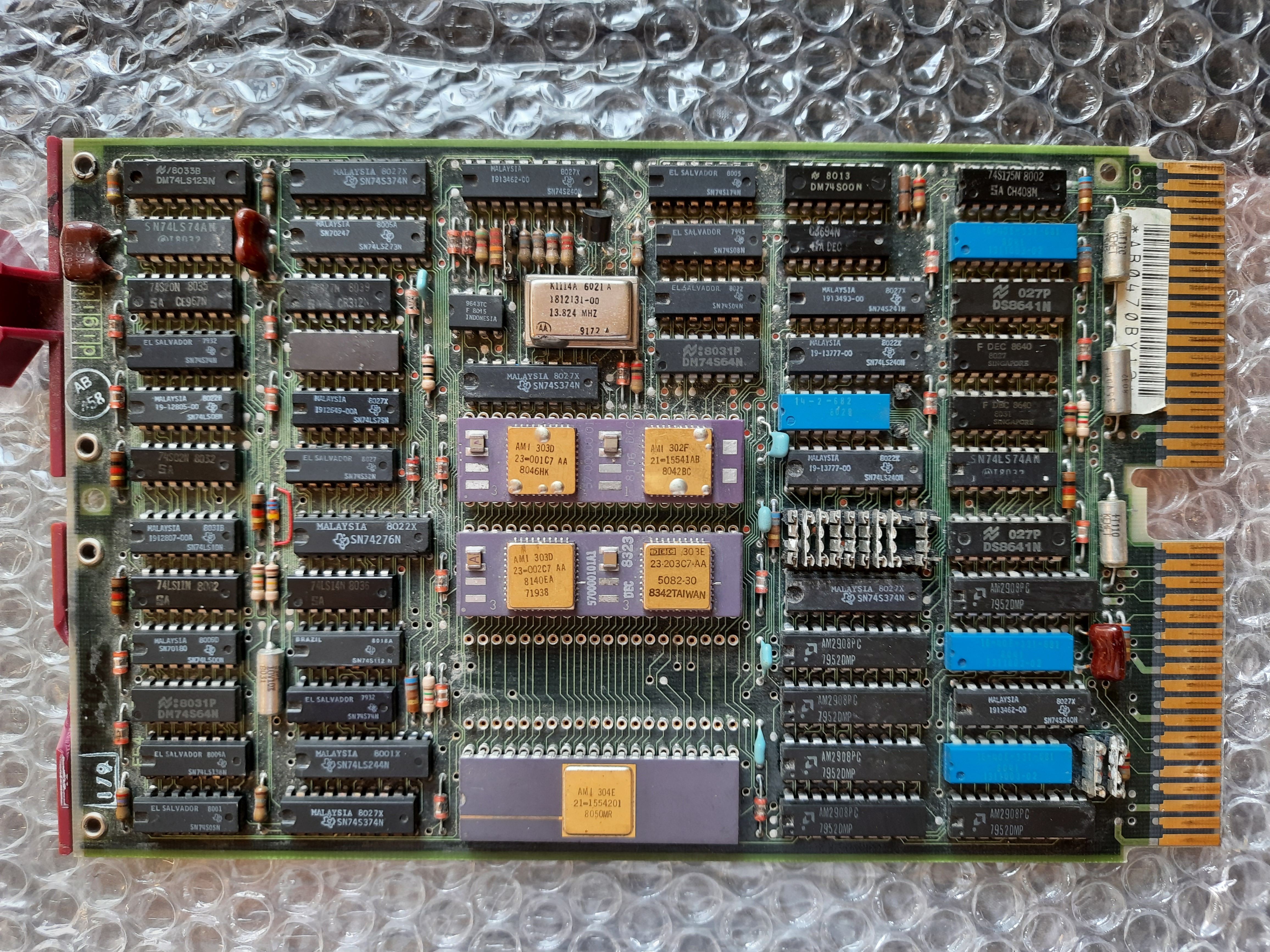
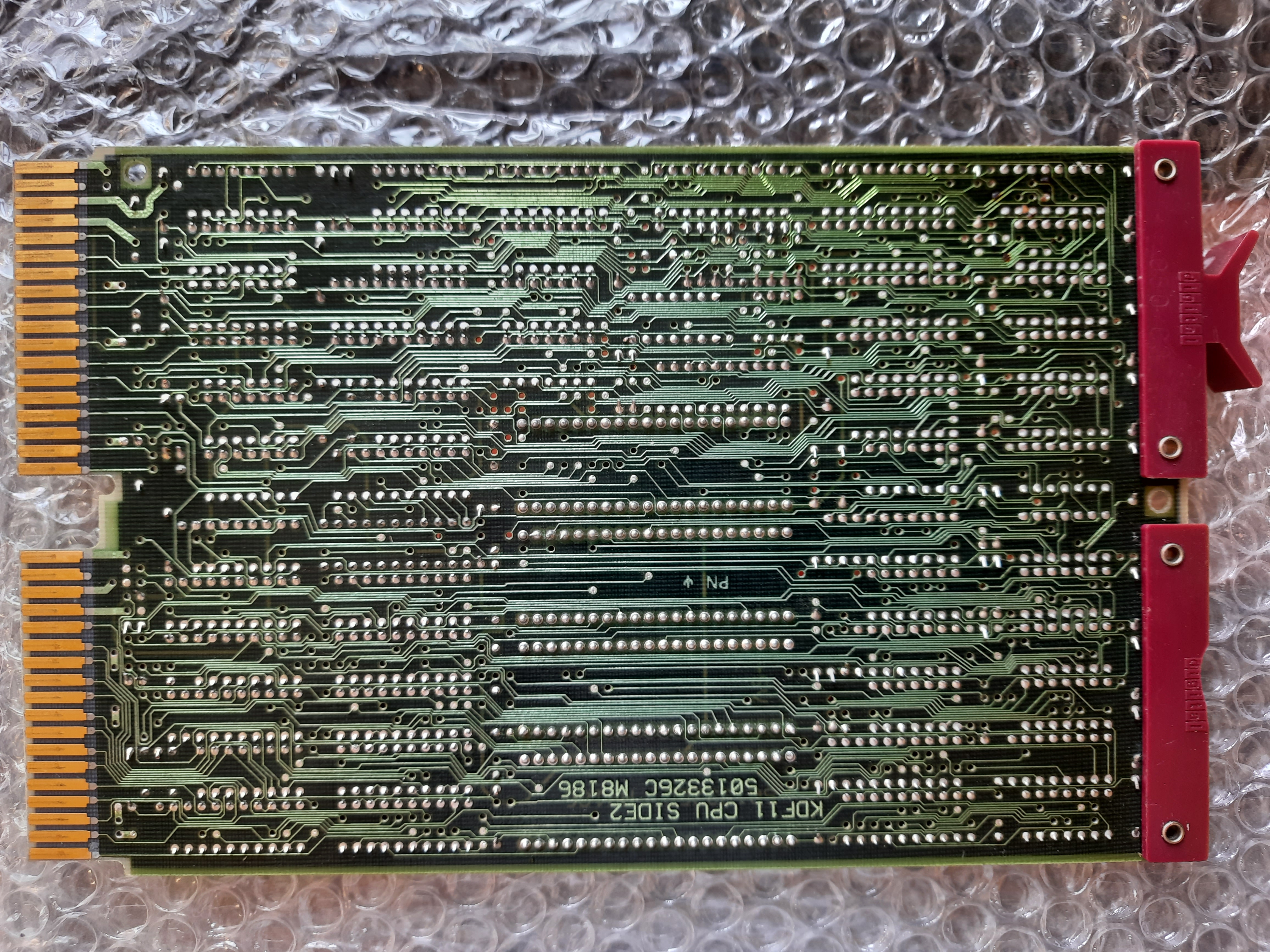
- M8186: LSI-11/23 CPU (C Revision, so capable of 22 bit adressing)
- M8044: MSV11-DD RAM, 18Bit
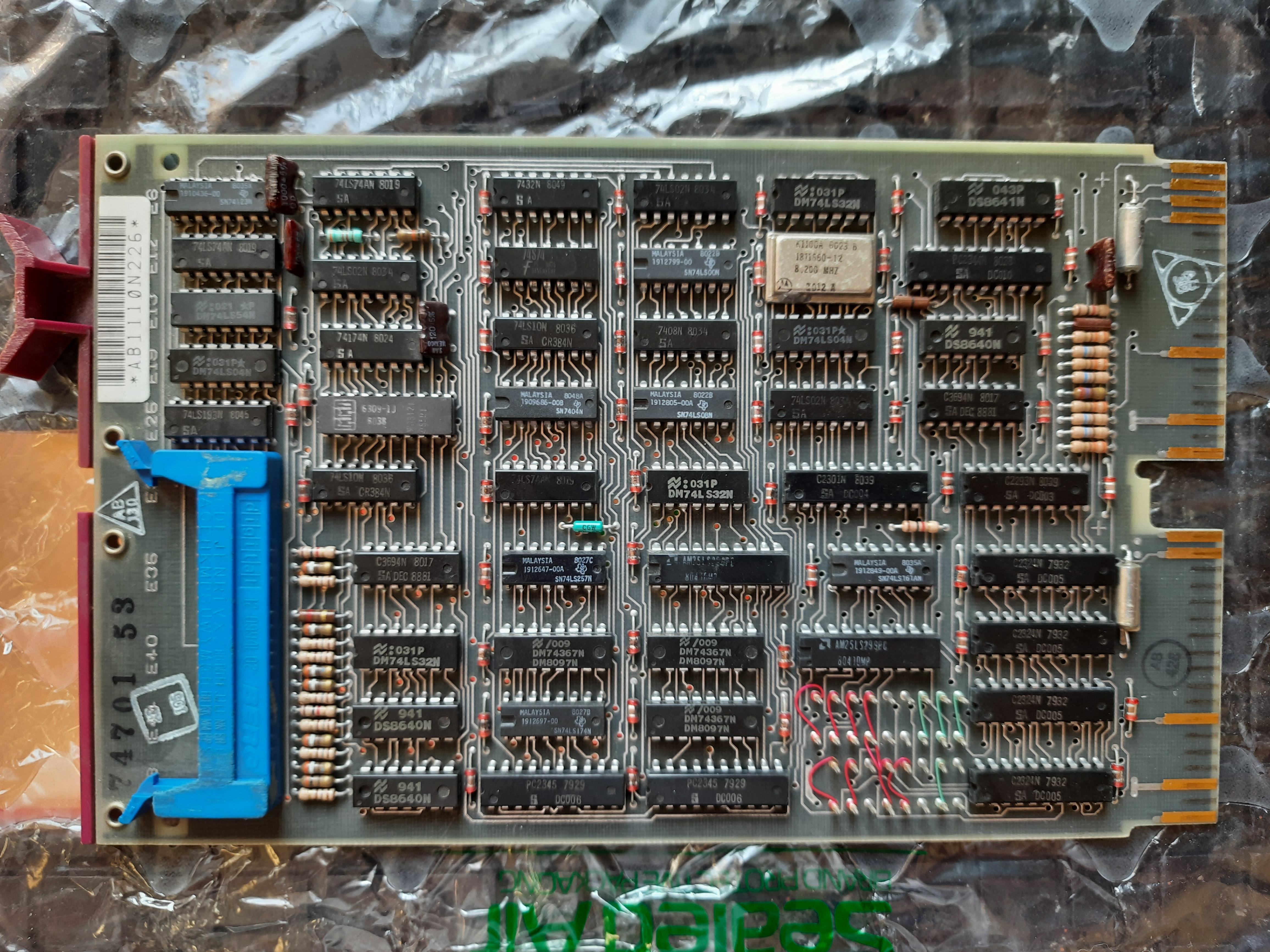
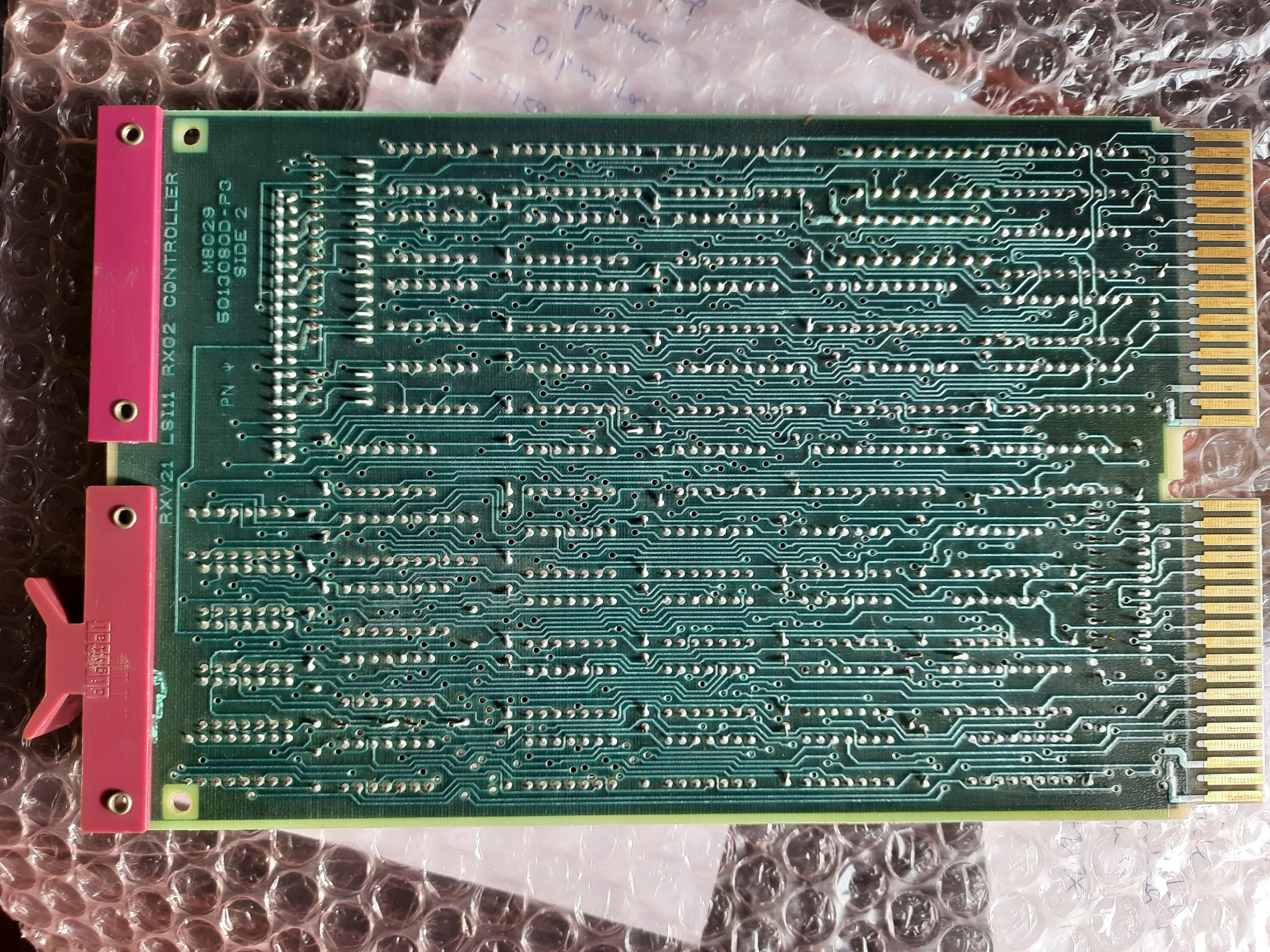
- M8029: RX02 Disk Controller, 18 Bit
- M8047: MXV11-A Multi Purpose Card, 18 Bit.
OBA11-MF means a BA11-MF mounting box is included. From manual:
BA 11-MF consists of BA 11-MC mounting box with H9270-A backplane and H780-F power supply for 230 Vac, 50 Hz.
H780-F, the “F” means console type “slave”. What that means, there is info on that in service manual, page 201.
BA11-MF mounting box
BA11-M mounting box, which can hold 4 quad-size cards, or 8 double sized cards.
Some operator interface at the right. Power Supply Unit, with two fans. At the back right is a fat transformer. Parts of the purple colored board handles are missing. Some info about the configurations for BA11 cages is here: https://gunkies.org/wiki/BA11-M_mounting_box
The PSU used is a H780, offering +5V at 18 A, and some 3.5 A at +12 volts. With 132 Watts output power, this is the smallest PSU DEC offered for these kind of machines.
ebay image:

ebay image:
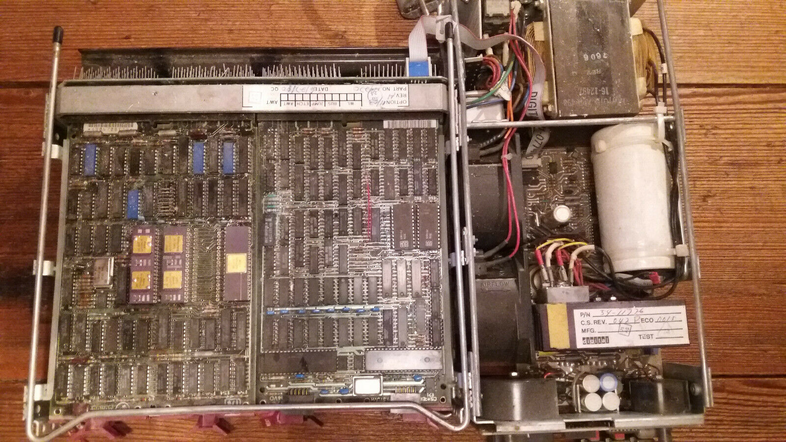
Device after some care-taking and cleaning:
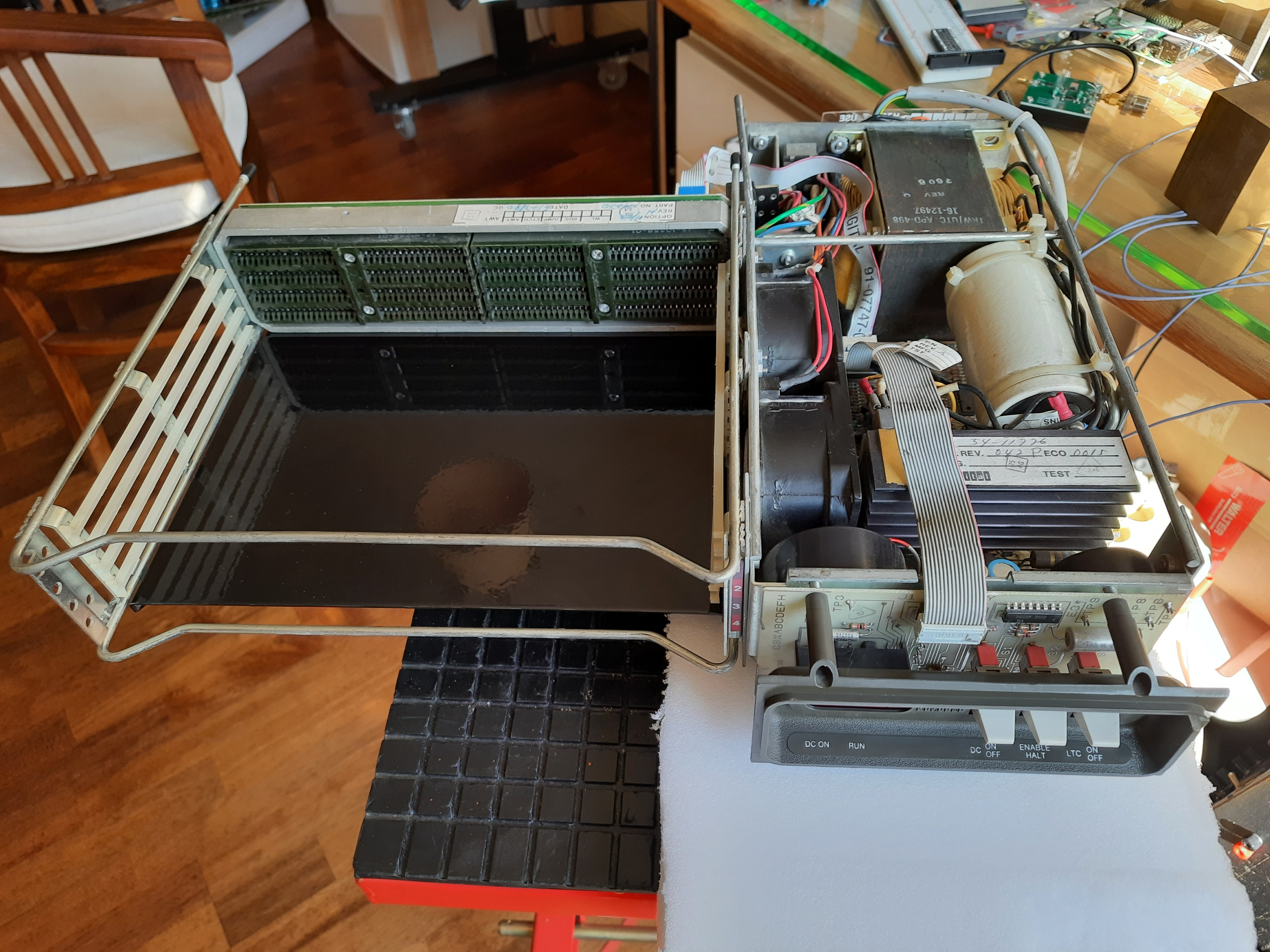
Full view, back. We see the backplane at the right. Also a fuse and a main switch at the left. Some control cable goes from the PSU and operator unit from the left to the back plane. This is not the power supply cabling, that is to be found at the bottom, not visible in these pictures.
ebay image:
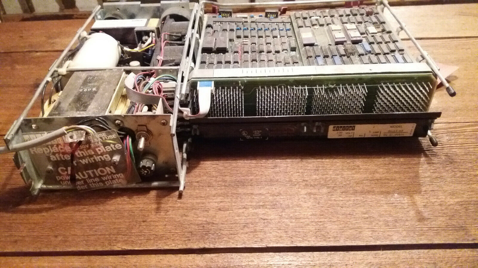
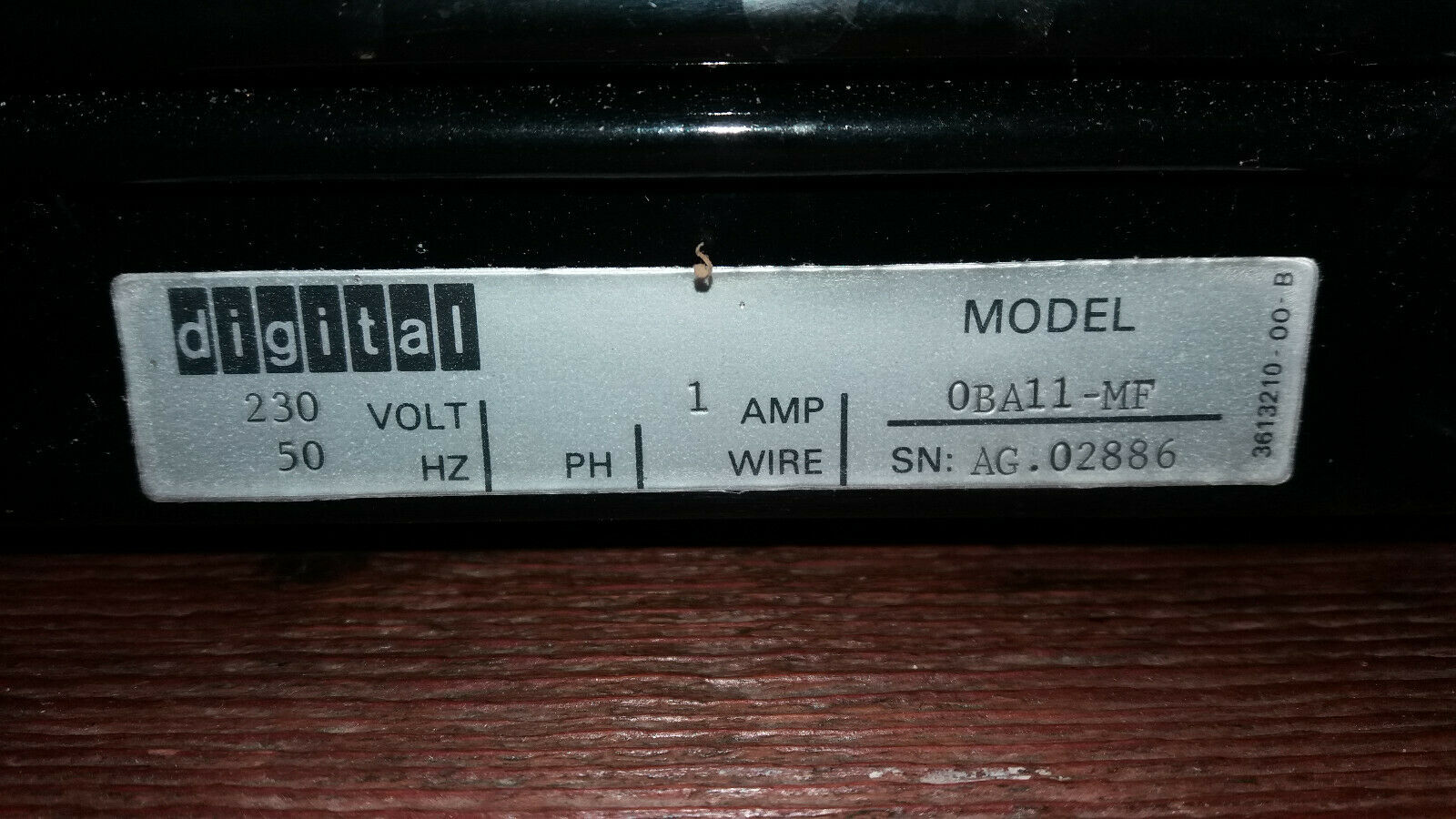
Model plate (ebay image):
M8186 CPU board
CPU Board. Beside the Fonz-CPU at the top, I can see a Floating Point Unit in the middle, nice. At the bottom is the MMU. Overall condition from ebay picture is not good, but after some cleaning it looked well.
On CPU card, one handle is broken. All other handles seem to be ok.
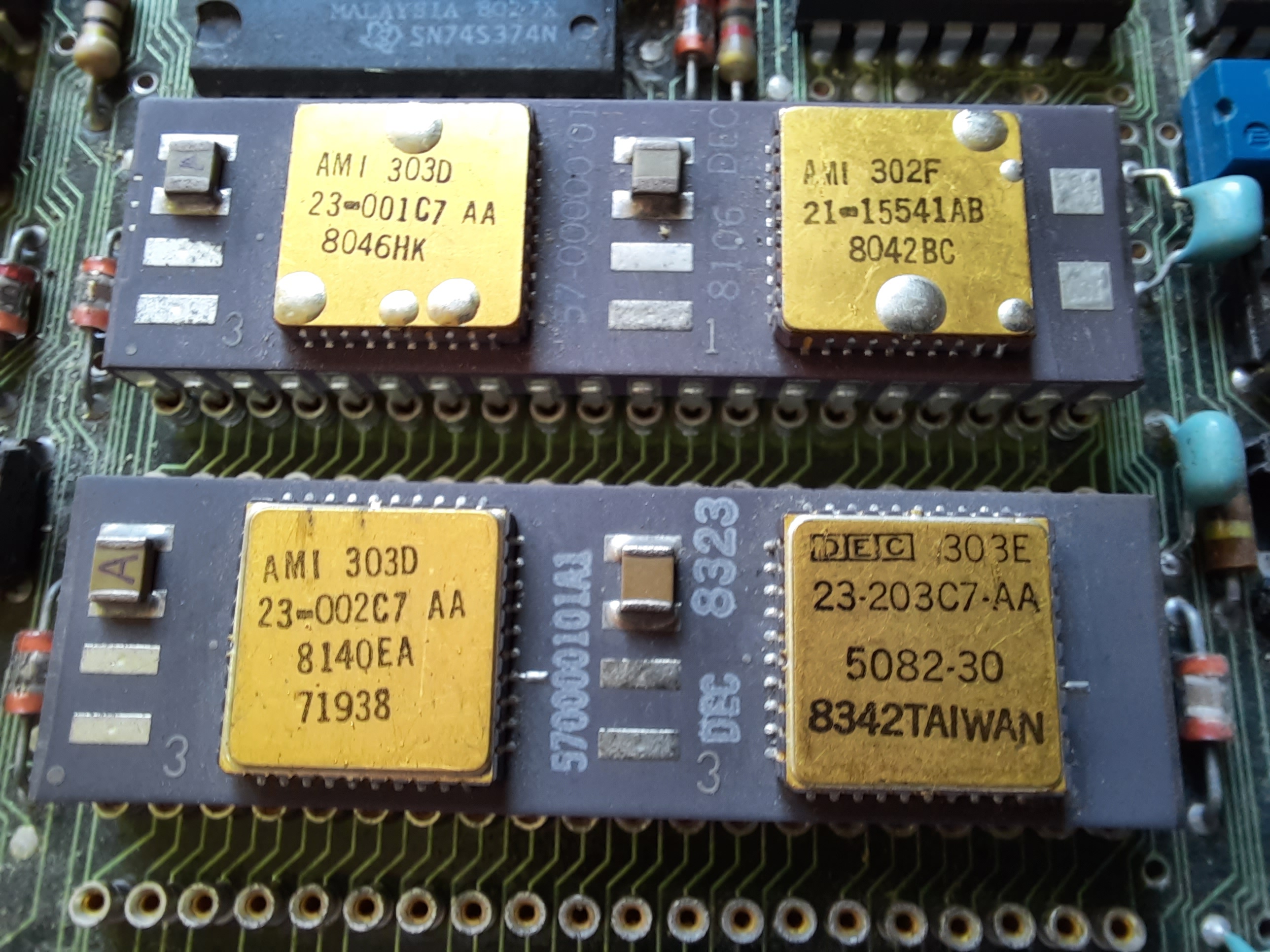
The FPU chip is a KEF11-AA floating point microcode options also called KEF11-AA floating point chip.
While the CPU contains EIS instruction microcode, the FIS instructions are contained in the FPU chip. So, if the FPU is inserted, it should be possible to execute FIS (floating point) instructions.
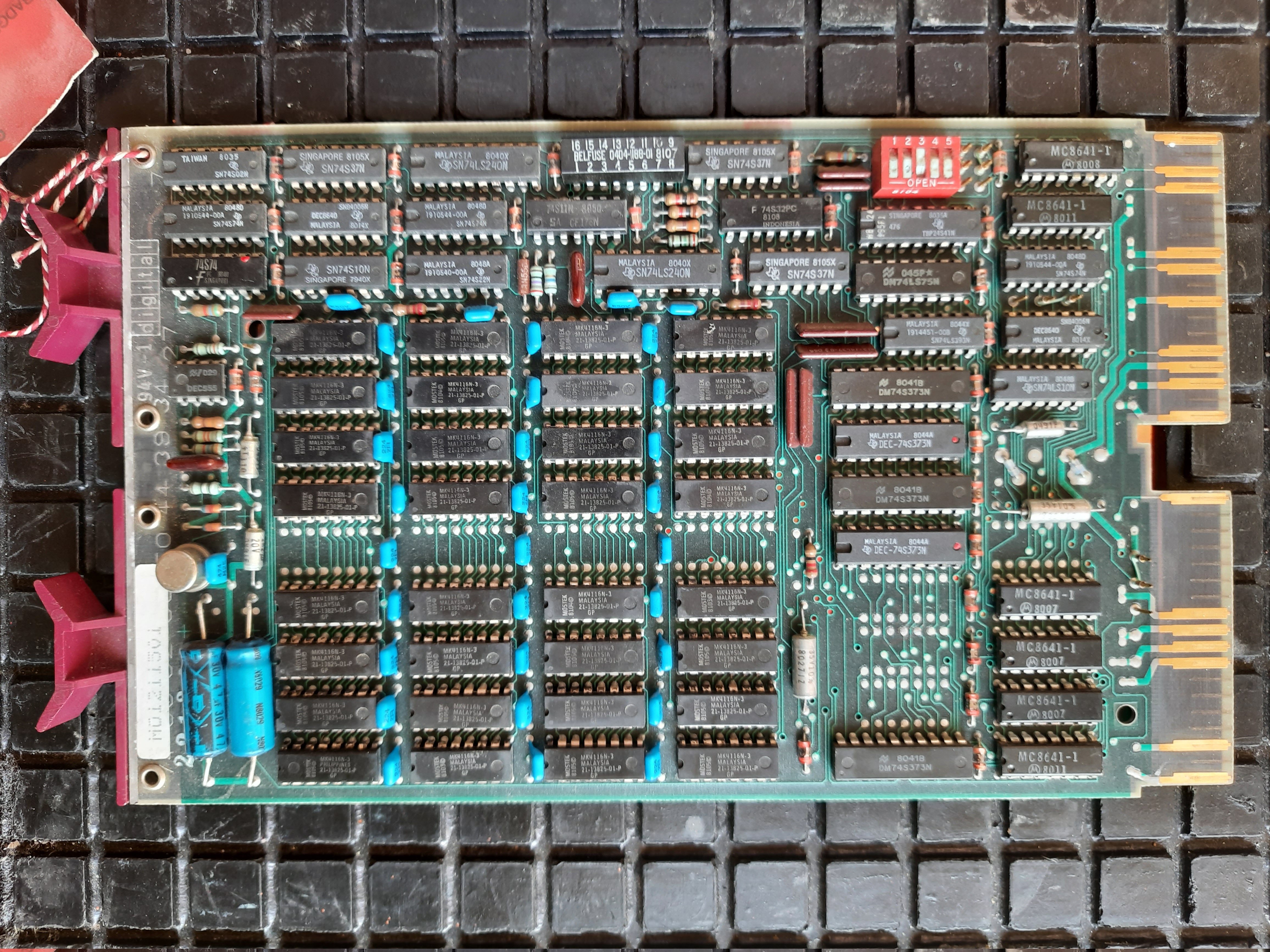
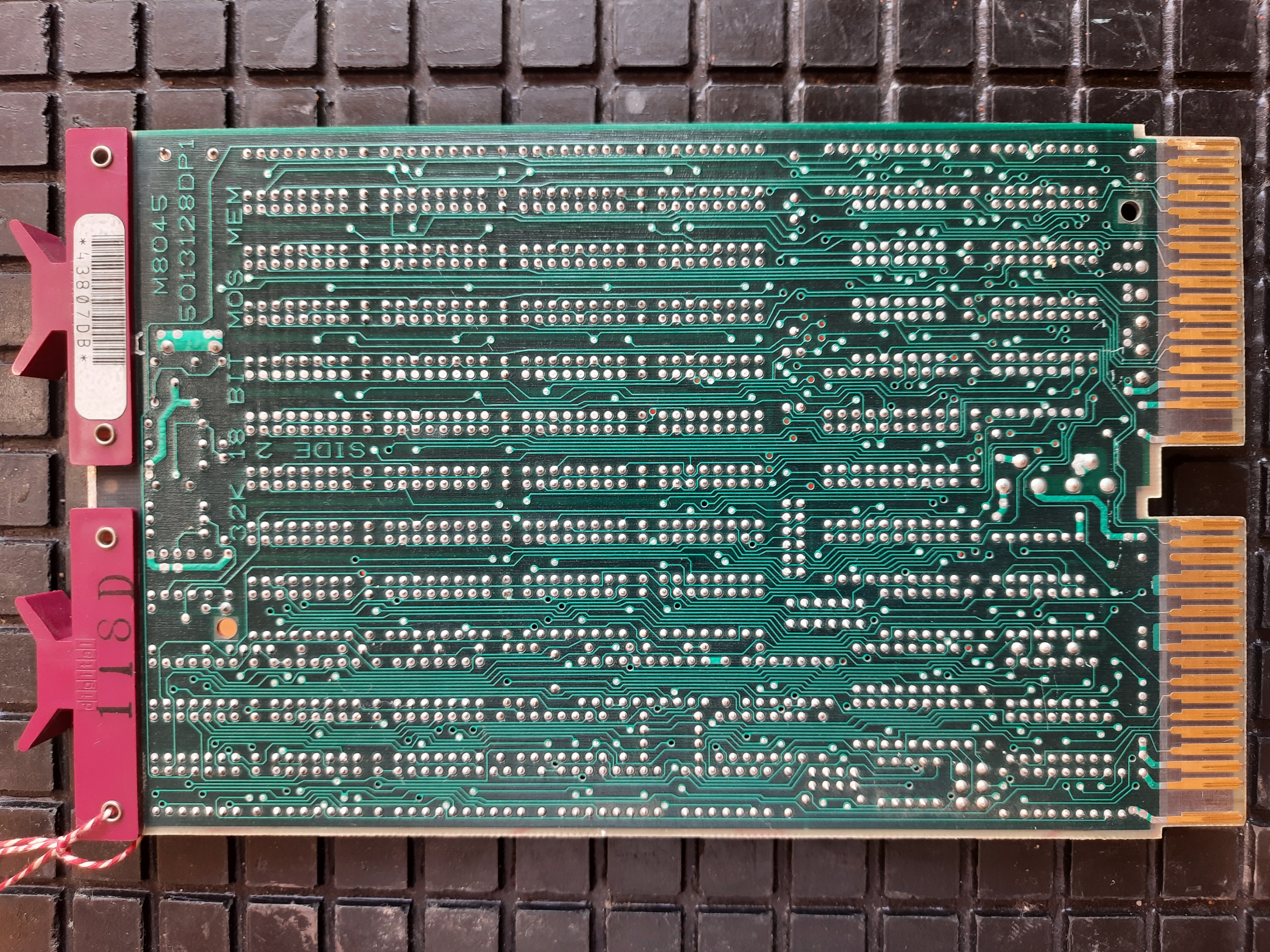
M8044 MSV11-DD RAM
RAM, 32K Words, 18Bit
RAM has a defective-Badge :-(
M8029 LSI11 RX02 Floppy Disk Controller
Dual Floppy Disk Controller, 18 Bit
M8047 MXV11-A Multi Purpose Card
This module offers:
- Two serial lines, one of them console compatible, 38.4KBit. Usually, a console and a tape drive were connected at these lines. 10 pin connectors.
- RAM. I have a C model, so 32KBytes RAM.
- Boot PROMS, two sockets for up to 2x4 KBytes. I could find the DEC part numbers 23-03901-00 and 23-04001-00 on them, which are 6341 Chips with 512x8 Bytes each. These ROMs are MXV 11-A2 Boot ROMs for RX02, RX01, or TU58
- A line time clock with 60 or 50 Hz
Mostek MK 4116-N3 RAM Chips. They have 16Kx1Bit. There are 16 chips on the board.
16Kx16 = 32Kx8.
So it is a board with 32 KBytes, but organized in 16-bit words. This means the board has 16K words.
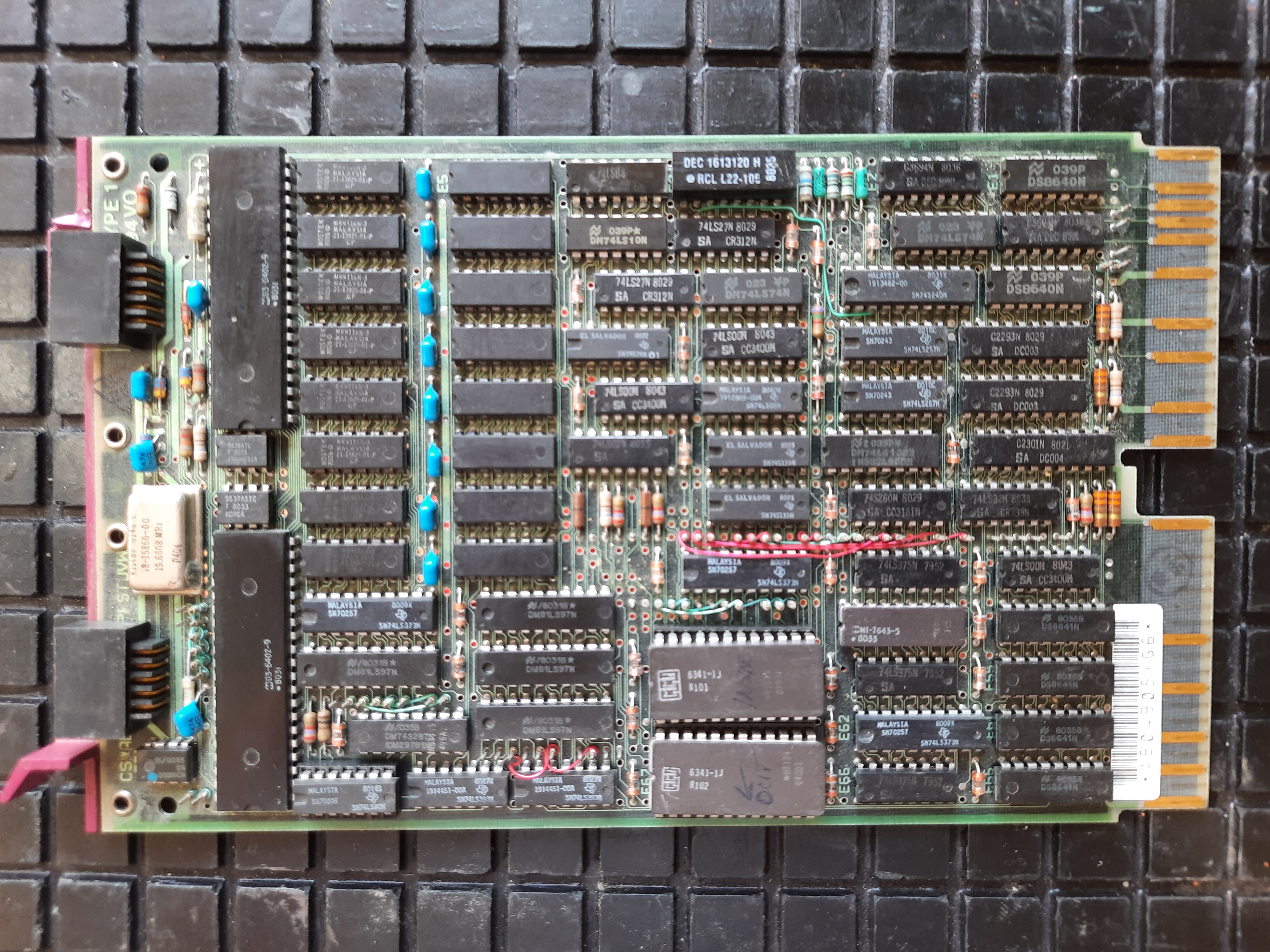
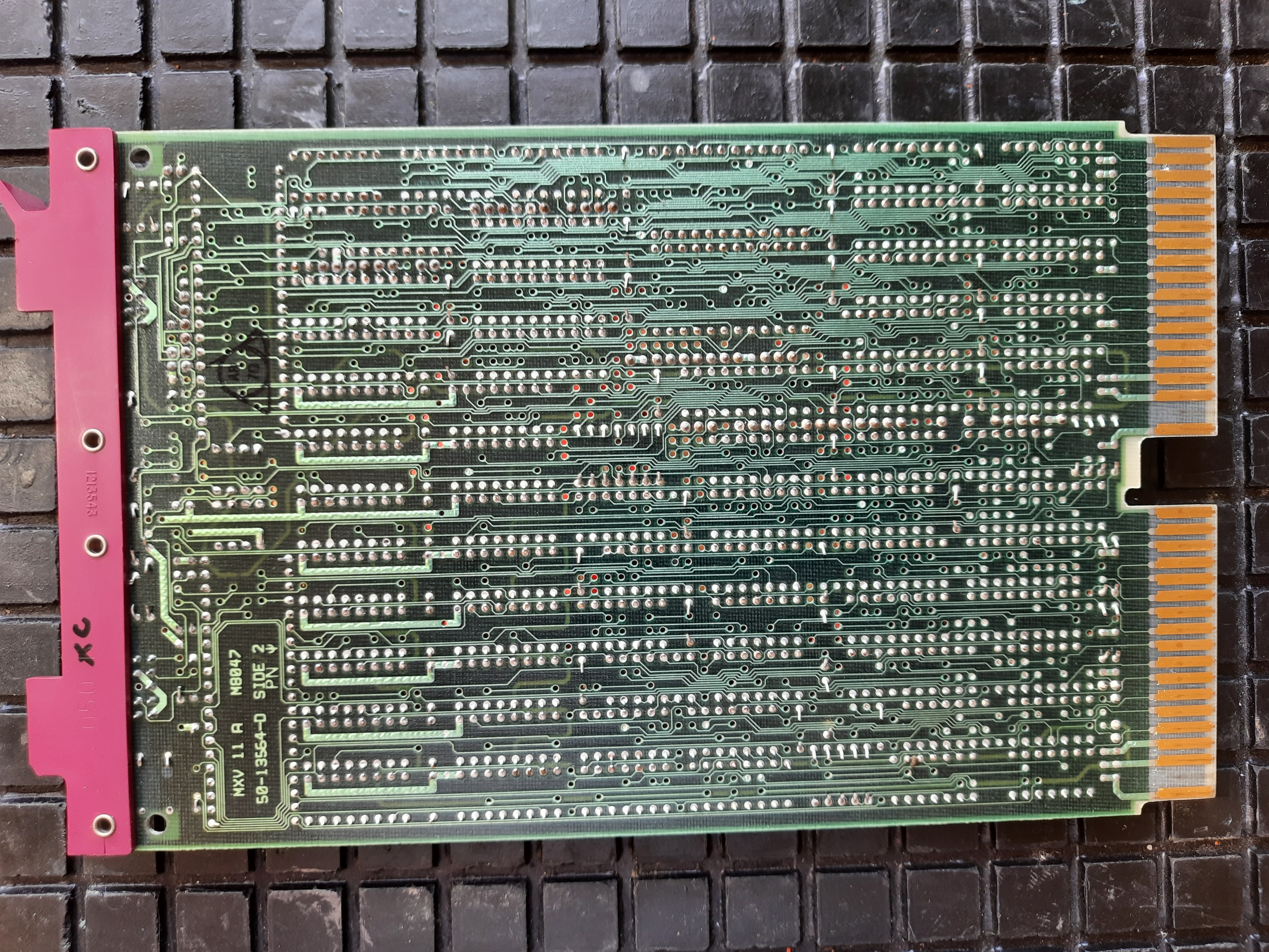
If a TU58 tape drive would be connected to one of the serial connectors, the ROMs would be able to boot an operating system from it. Interesting fact, but the board has more than 60 jumpers and at first I will ignore it.
Another DEC Power Supply
With the OBA11-MF system, I also got as free give-away some DEC Power Supply Board. First I’ve put it aside because I though it was from a disk cabinet, because it is listed as being the PSU for DEC 11/150 Dual Disk Drive Unit.
Later I found that it is the H7833 PSU unit, which is indeed used in the disk drive unit. But also in some small system PDP11 versions. This is described and shown here as BA11-VA Small System Box
So the PSU is capable of supplying a small PDP11 system- Maximum 5 volts power is 5.6 Ampere, and 12 volts power is 1.6 ampere.
So it can not supply many cards, only a few.
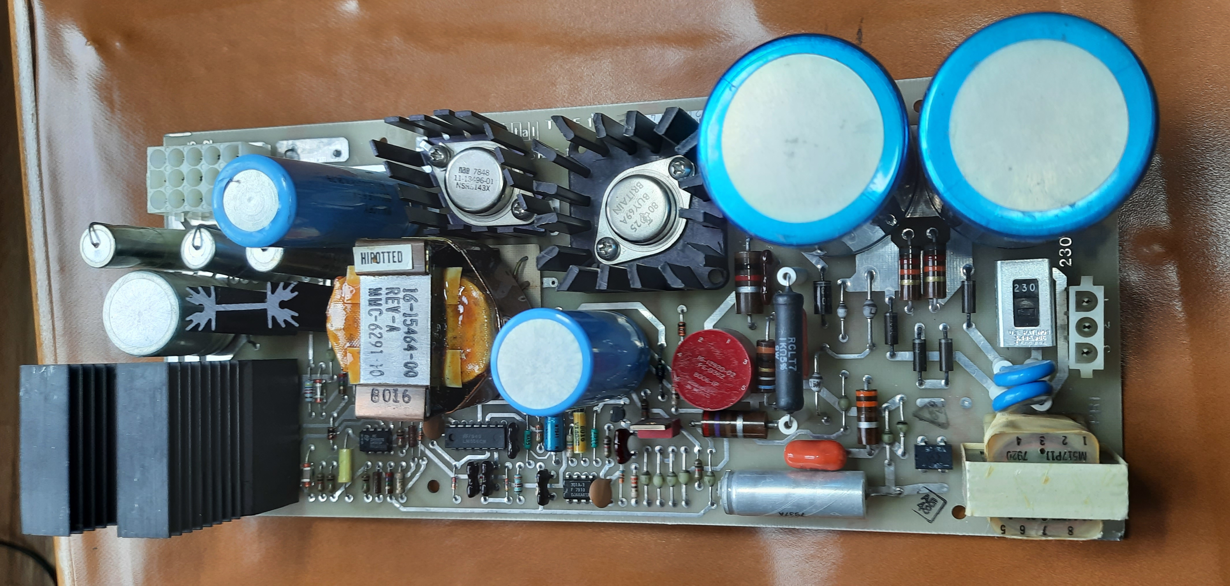 H7833 PSU unit
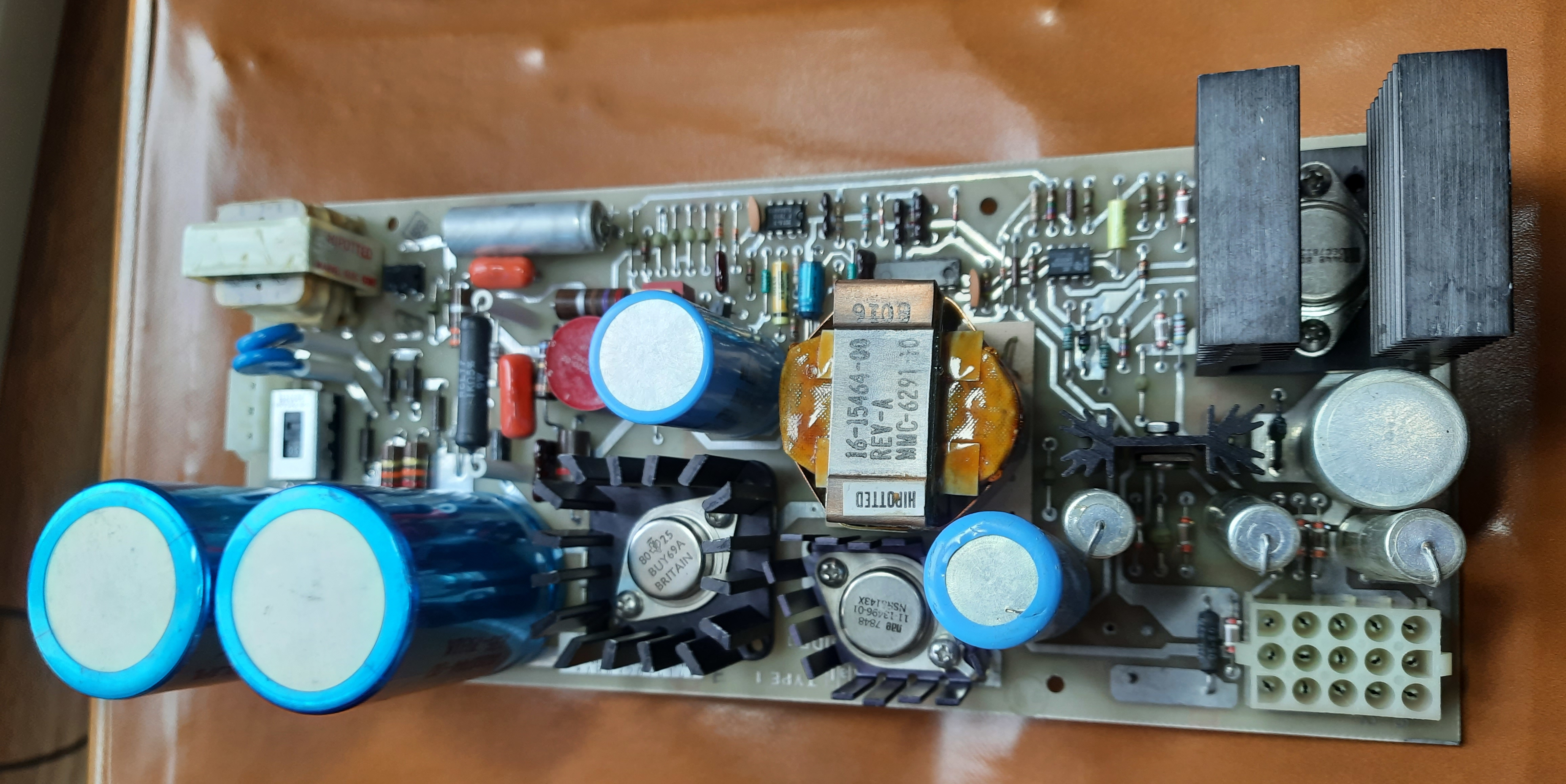
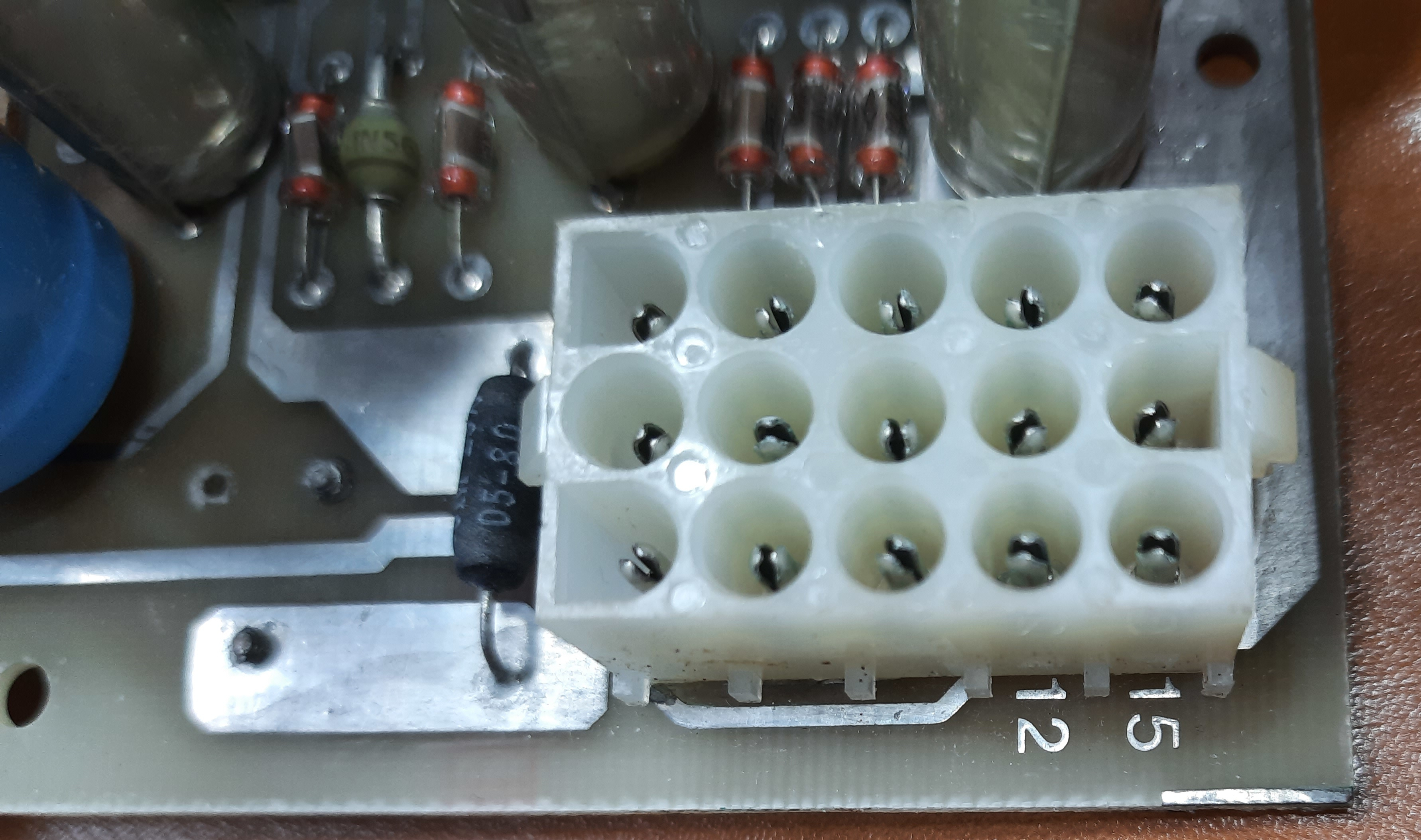
Output voltages connector
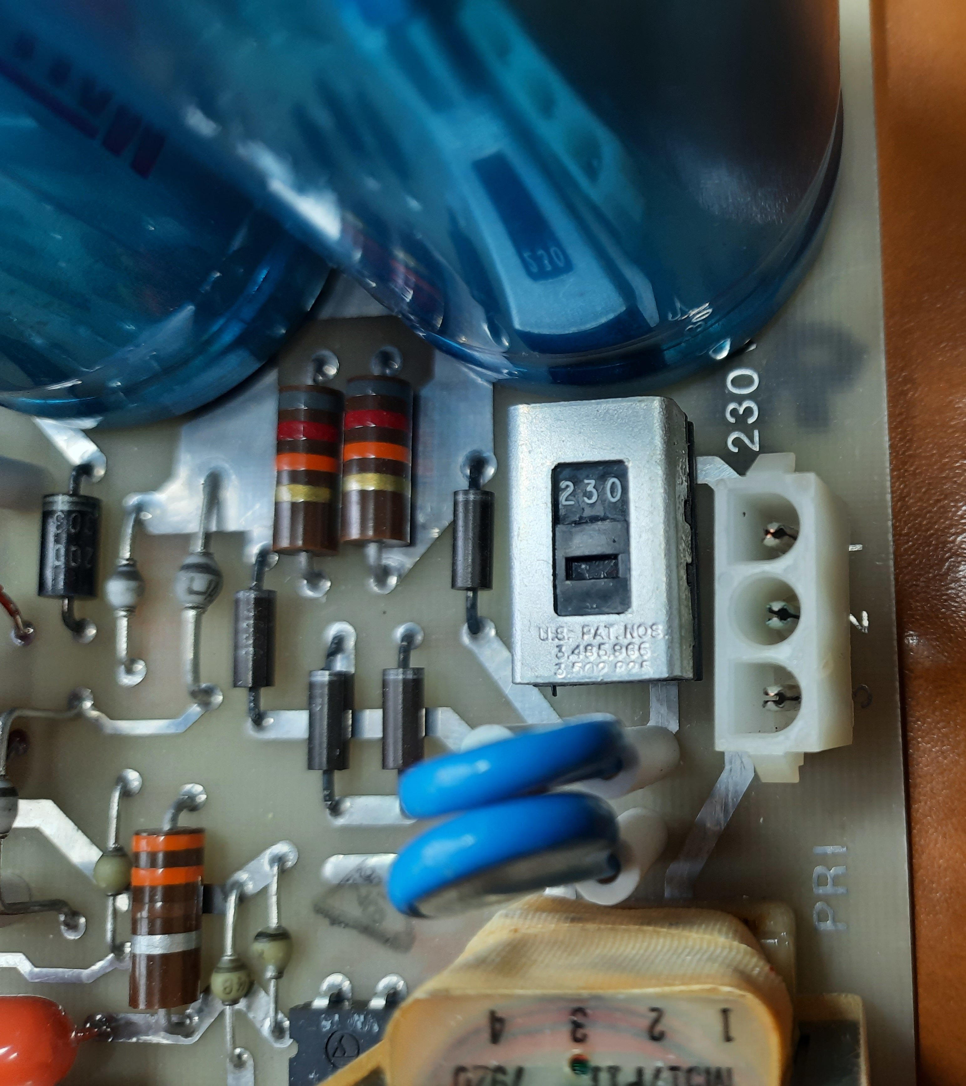
line supply input
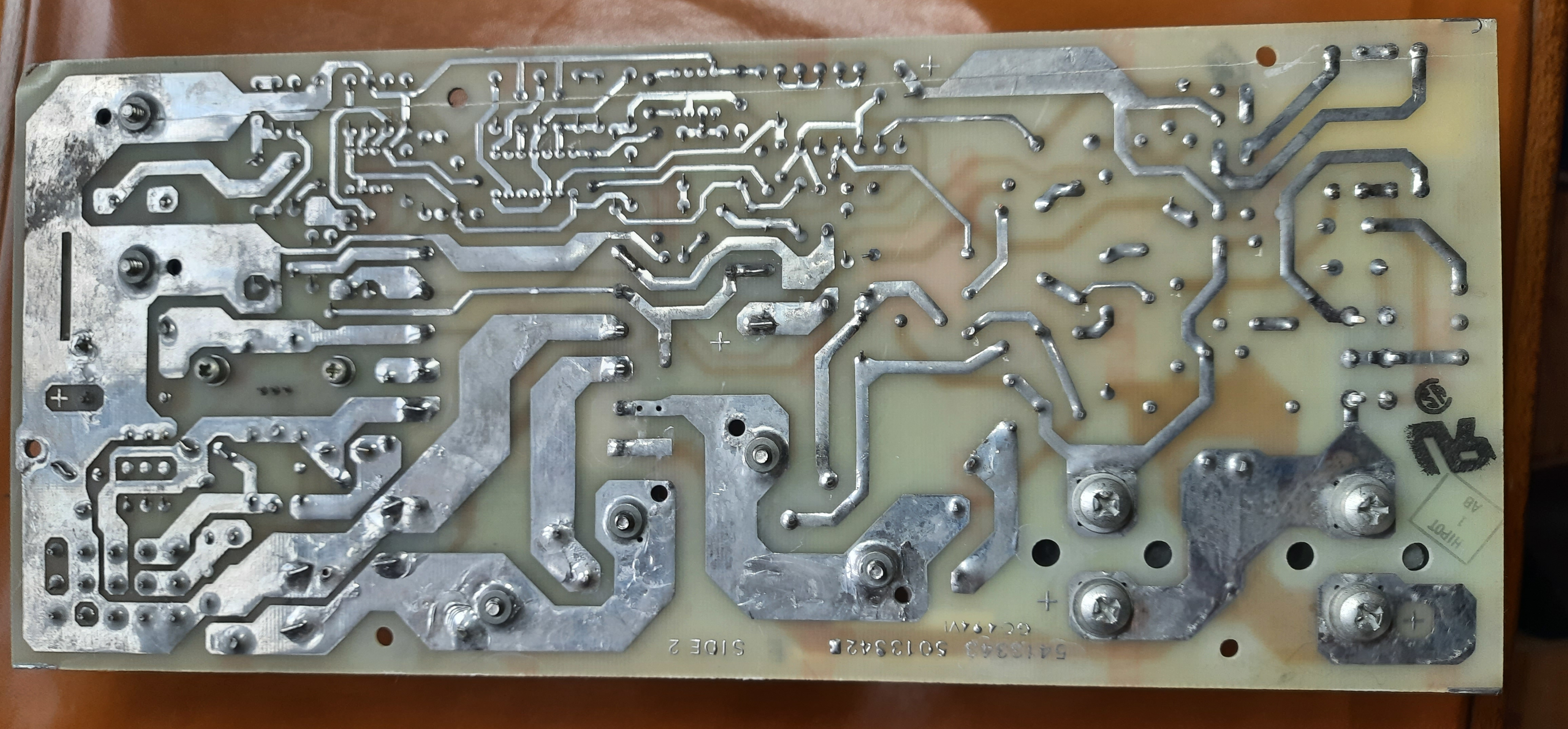
Solder side of PSU
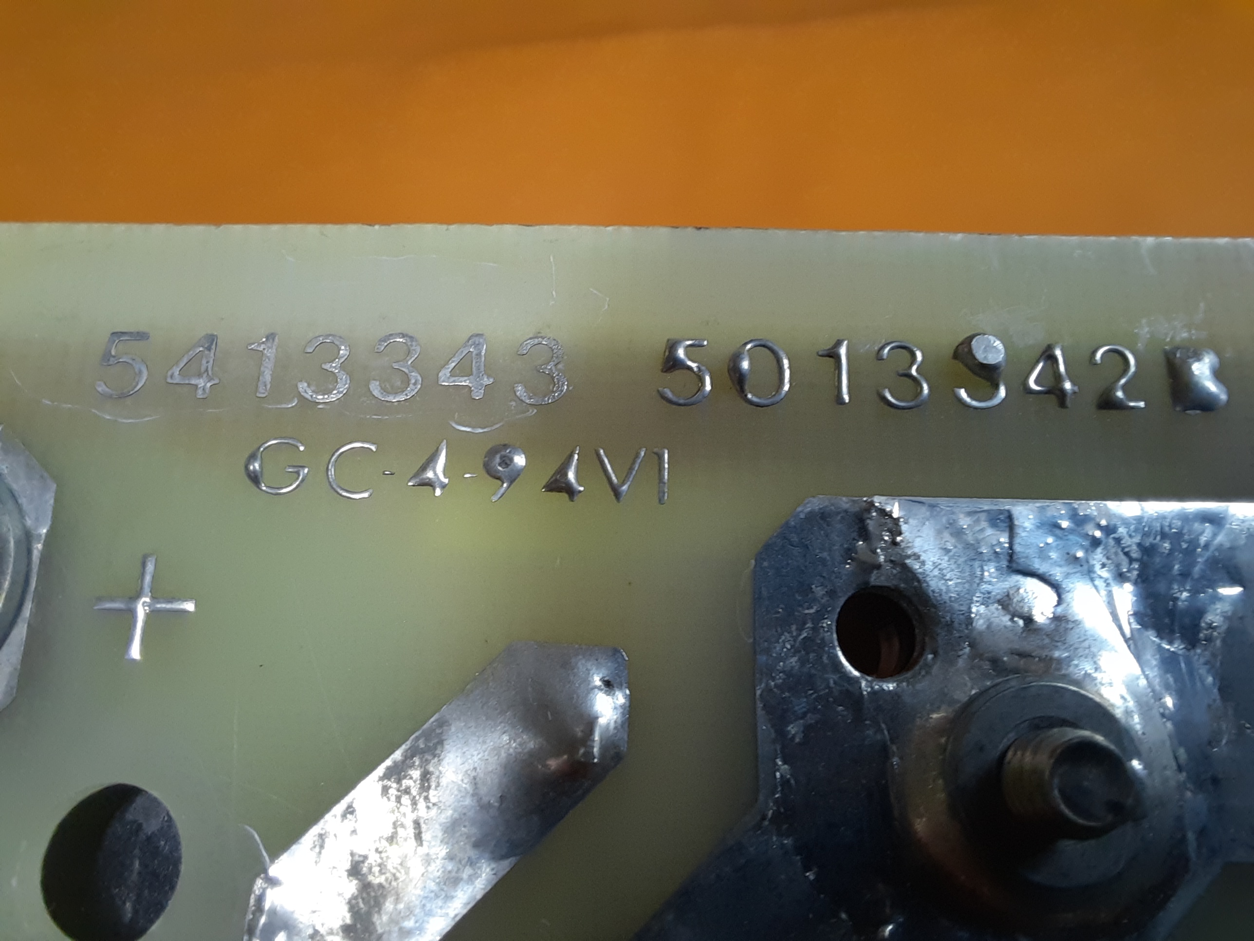
Board number 5413343, which maps to H7833 PSU.
So this board could be used, I need to check if it is working. Schematics and more can be found in PDT 11/150 Technical Manual .
More images
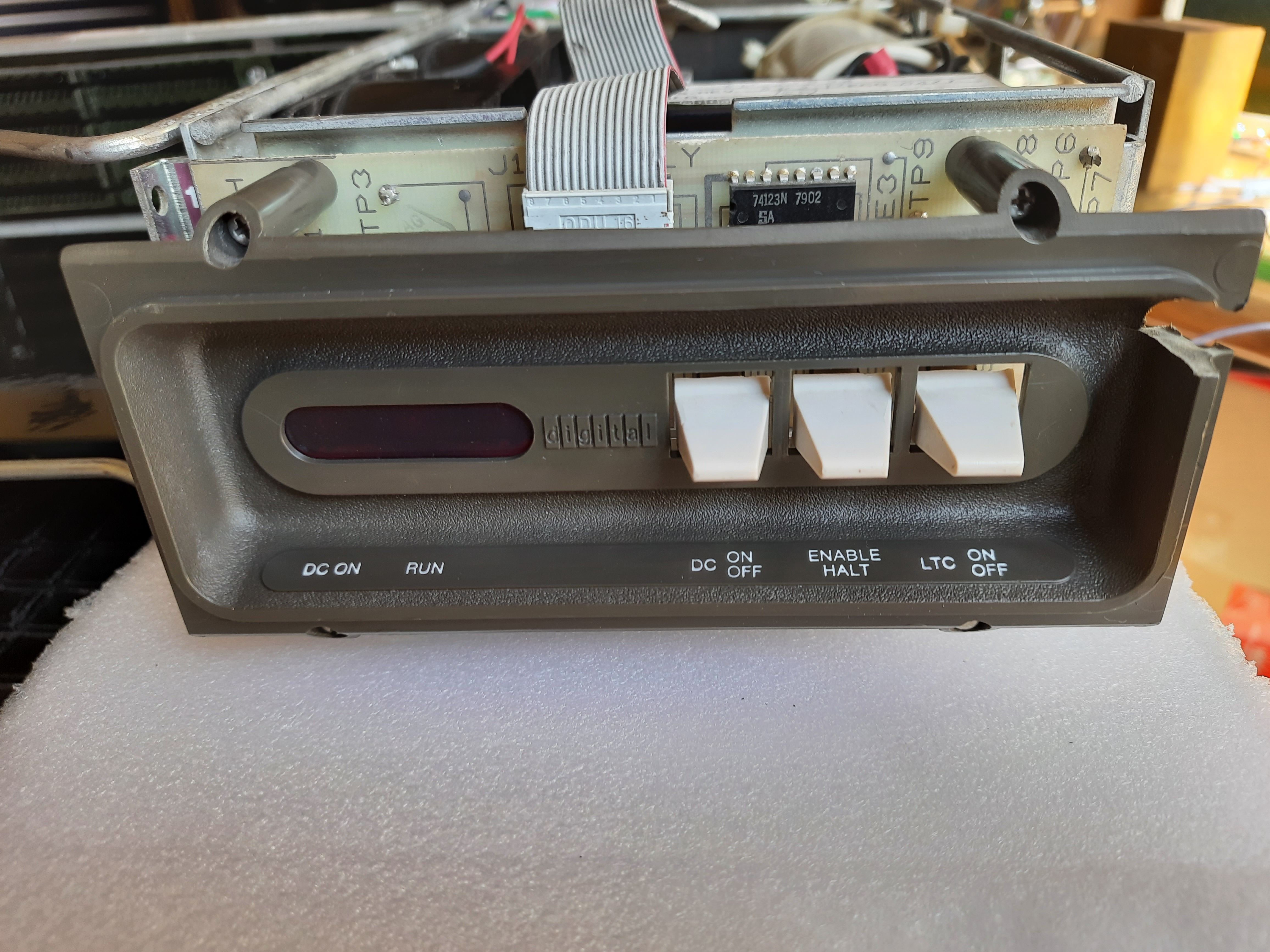
Front plate. I never owned something like this so far. Two Lights, for DC ON and RUN. Three switches DC ON/OFF, Enable/HALT, LTC (Line Time Clock) ON/OFF. A little damage at top right.
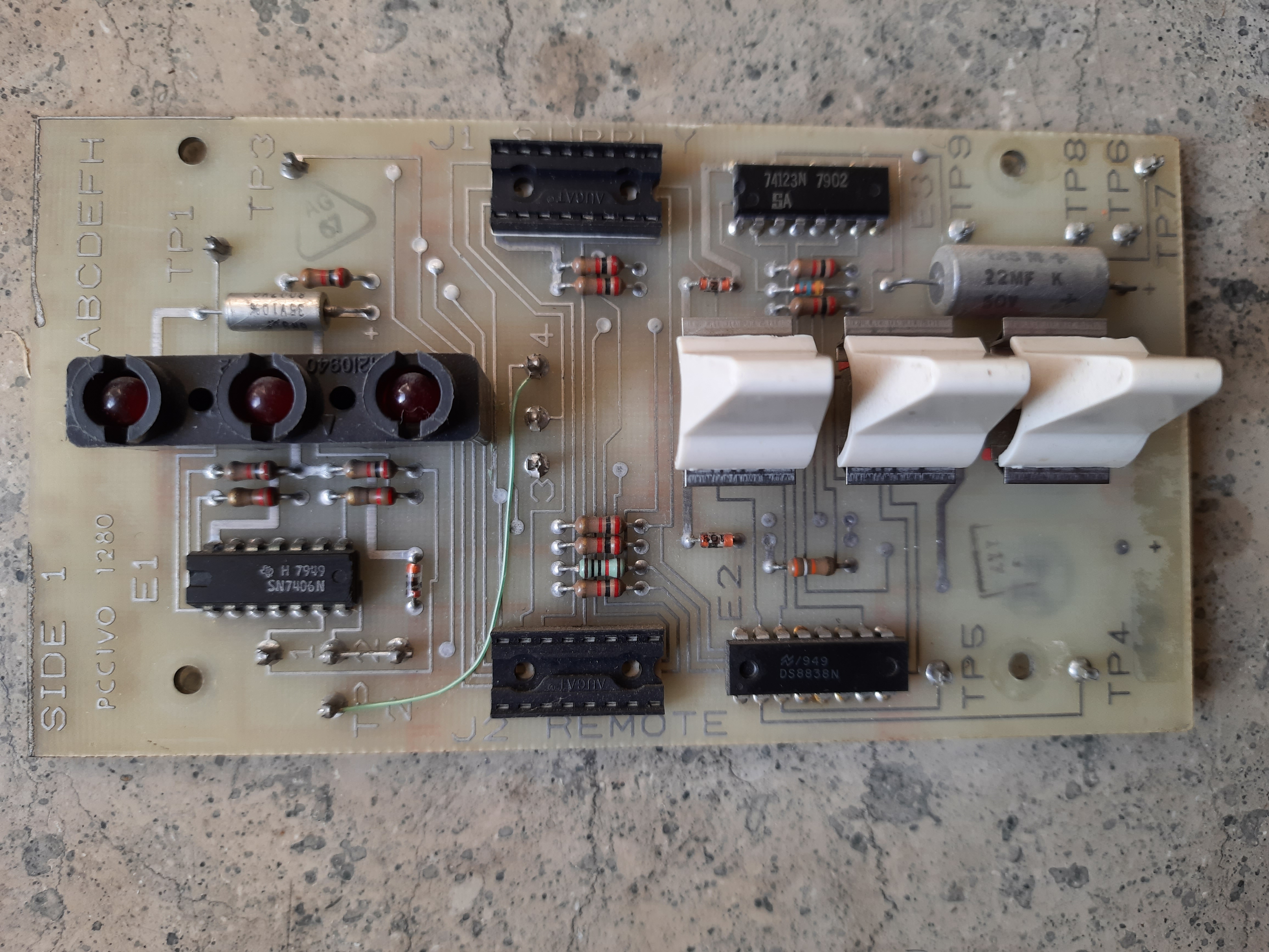
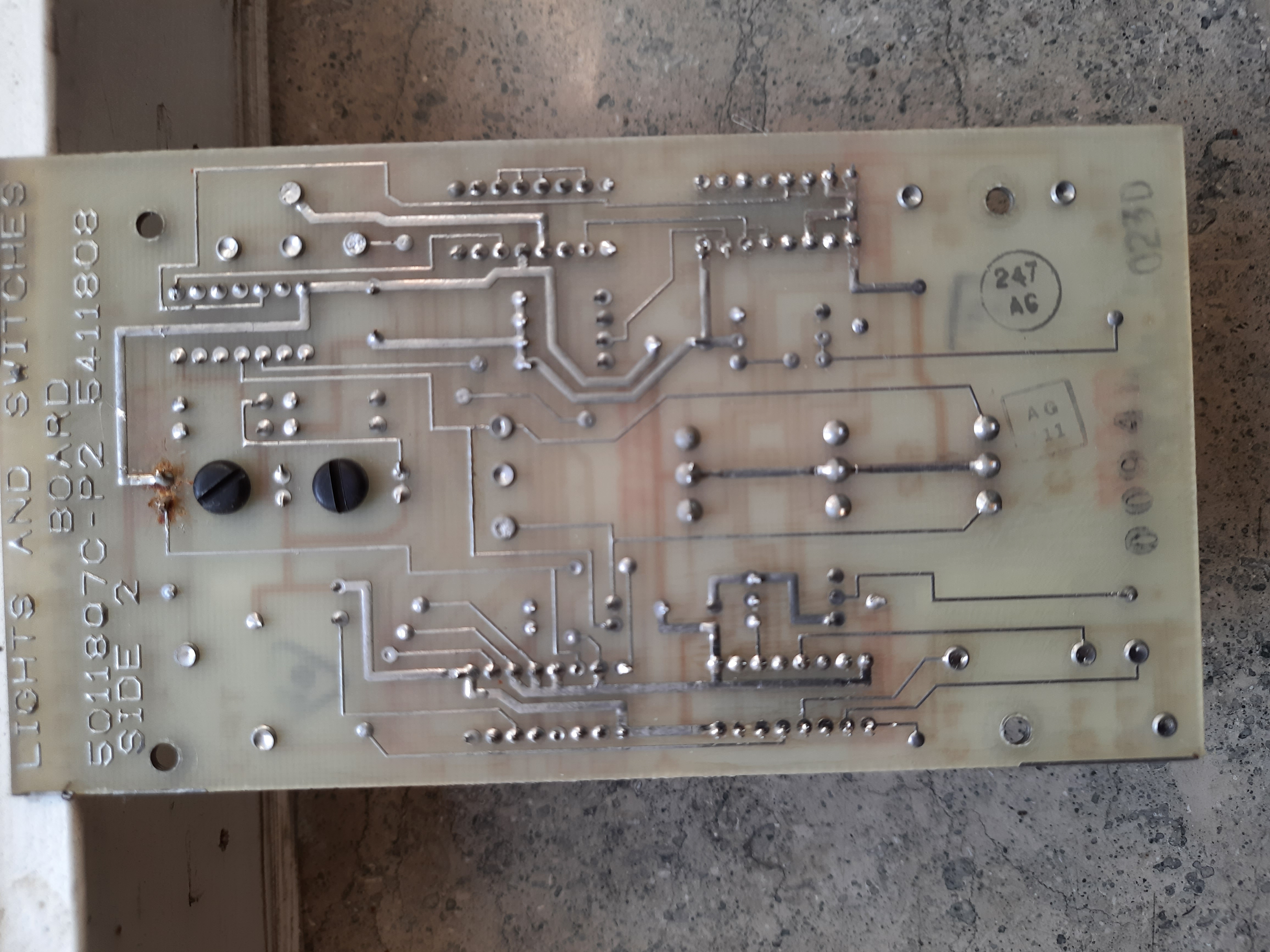
Switches and Lights board
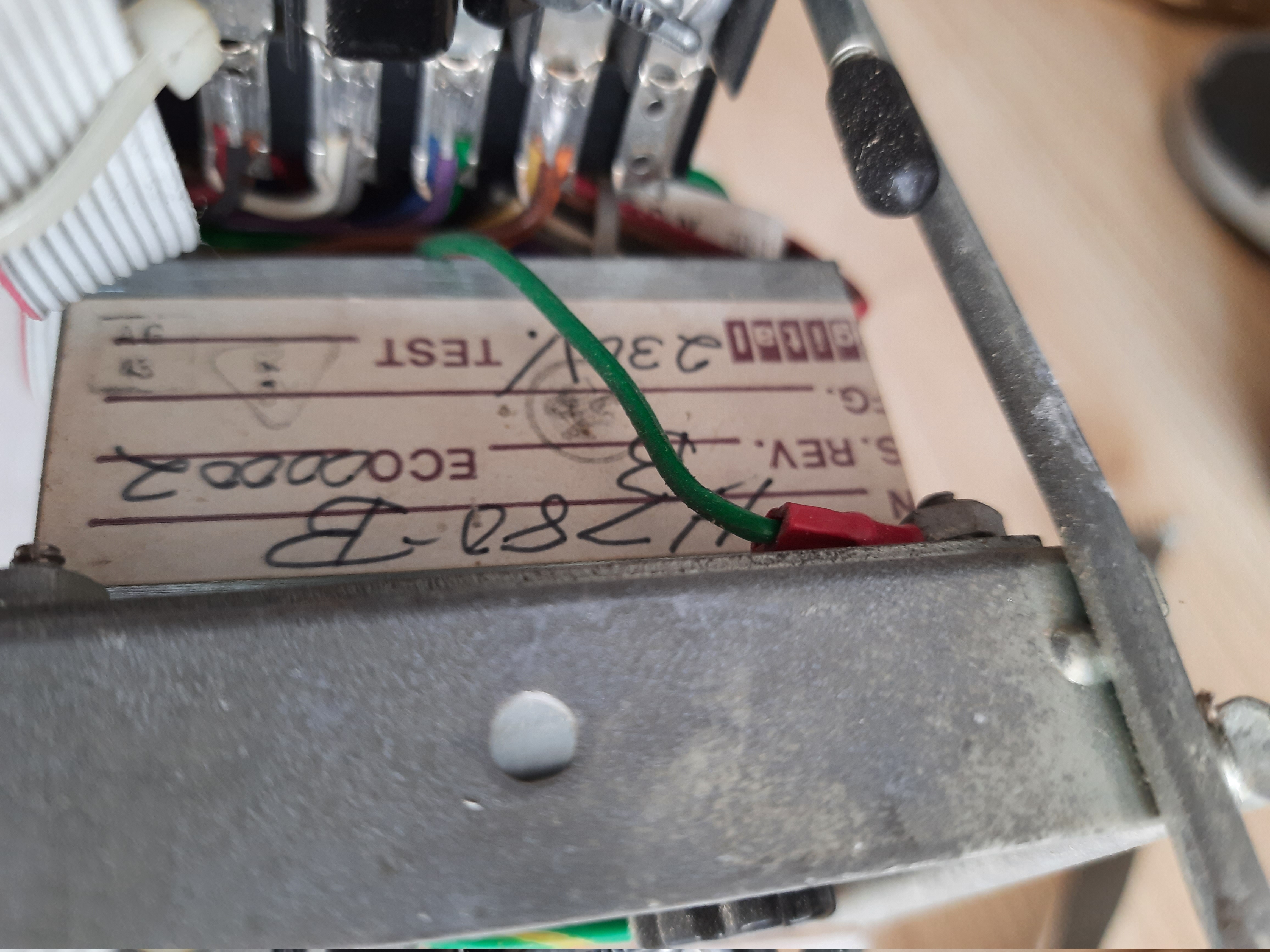
PSU type plate
BA11 is connected with 4 scews to PSU.
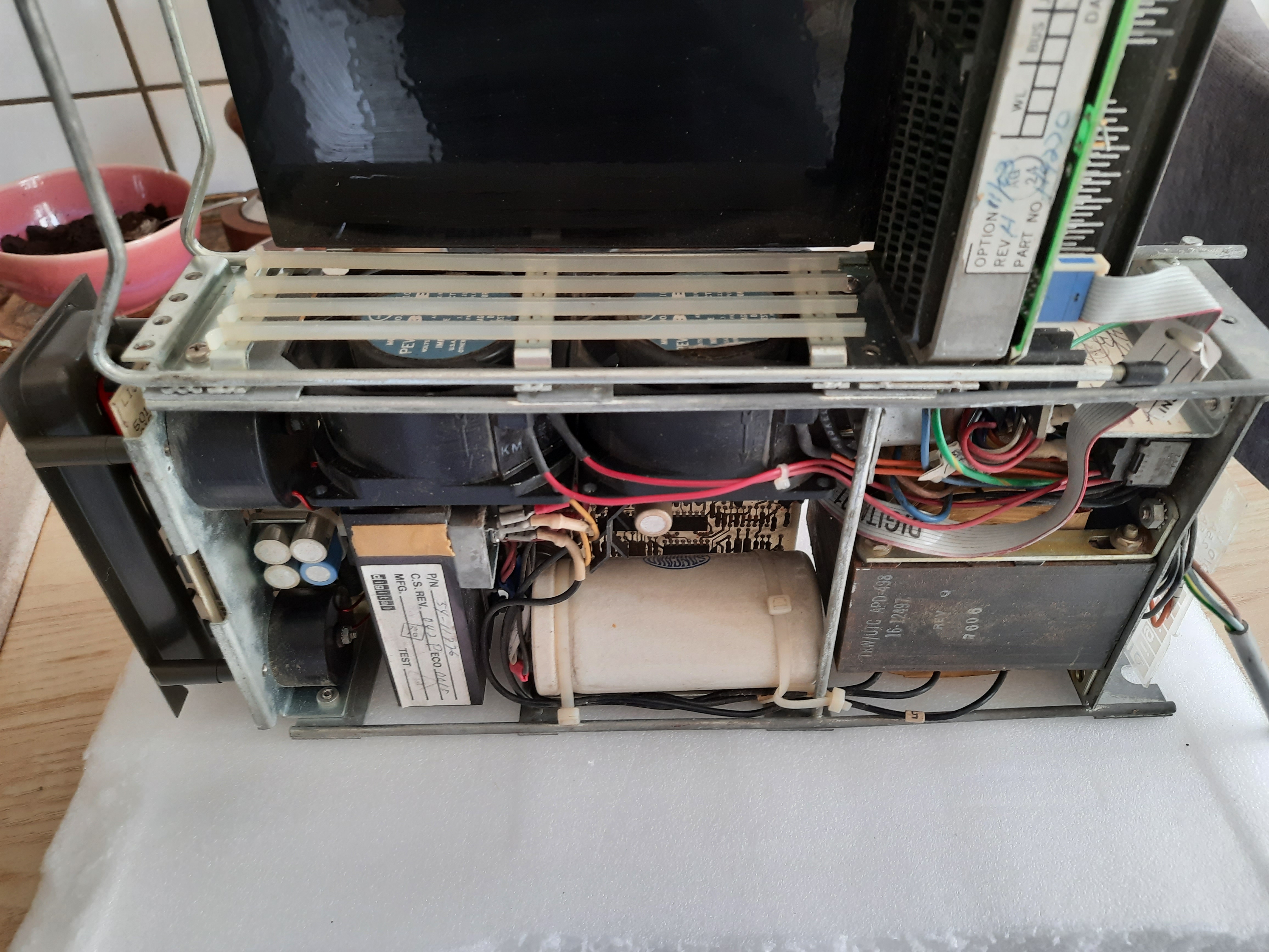
Backplane
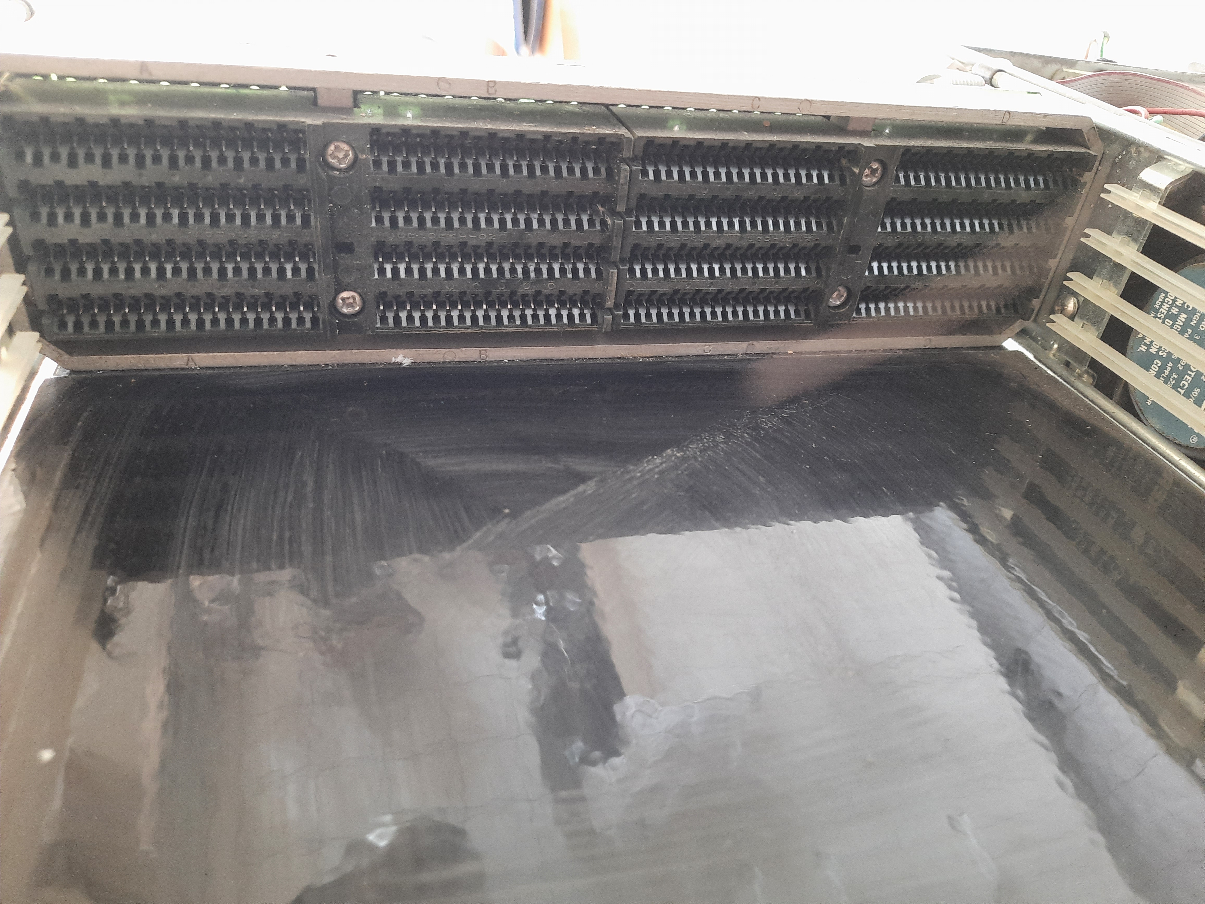
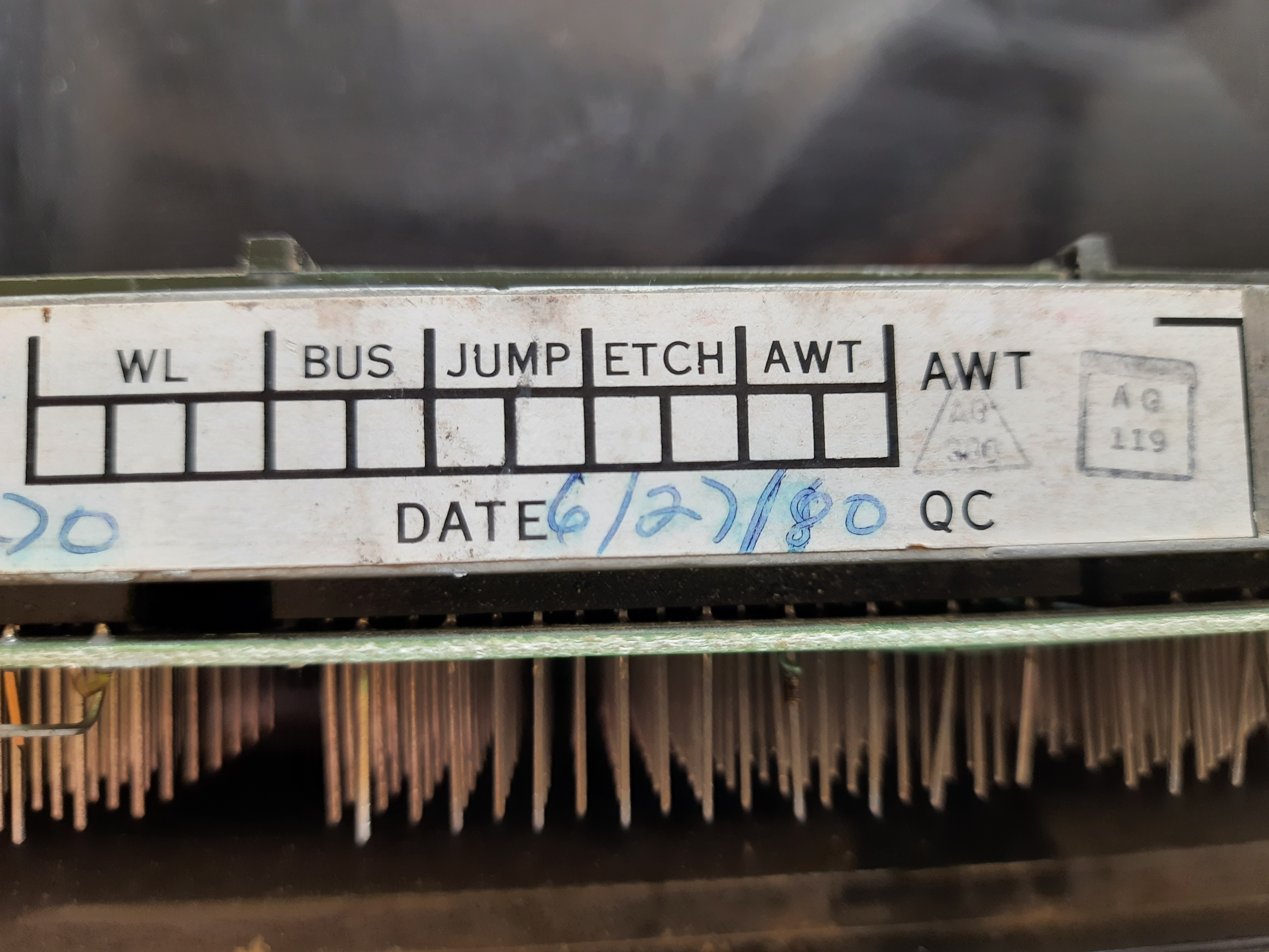
Backplane detail
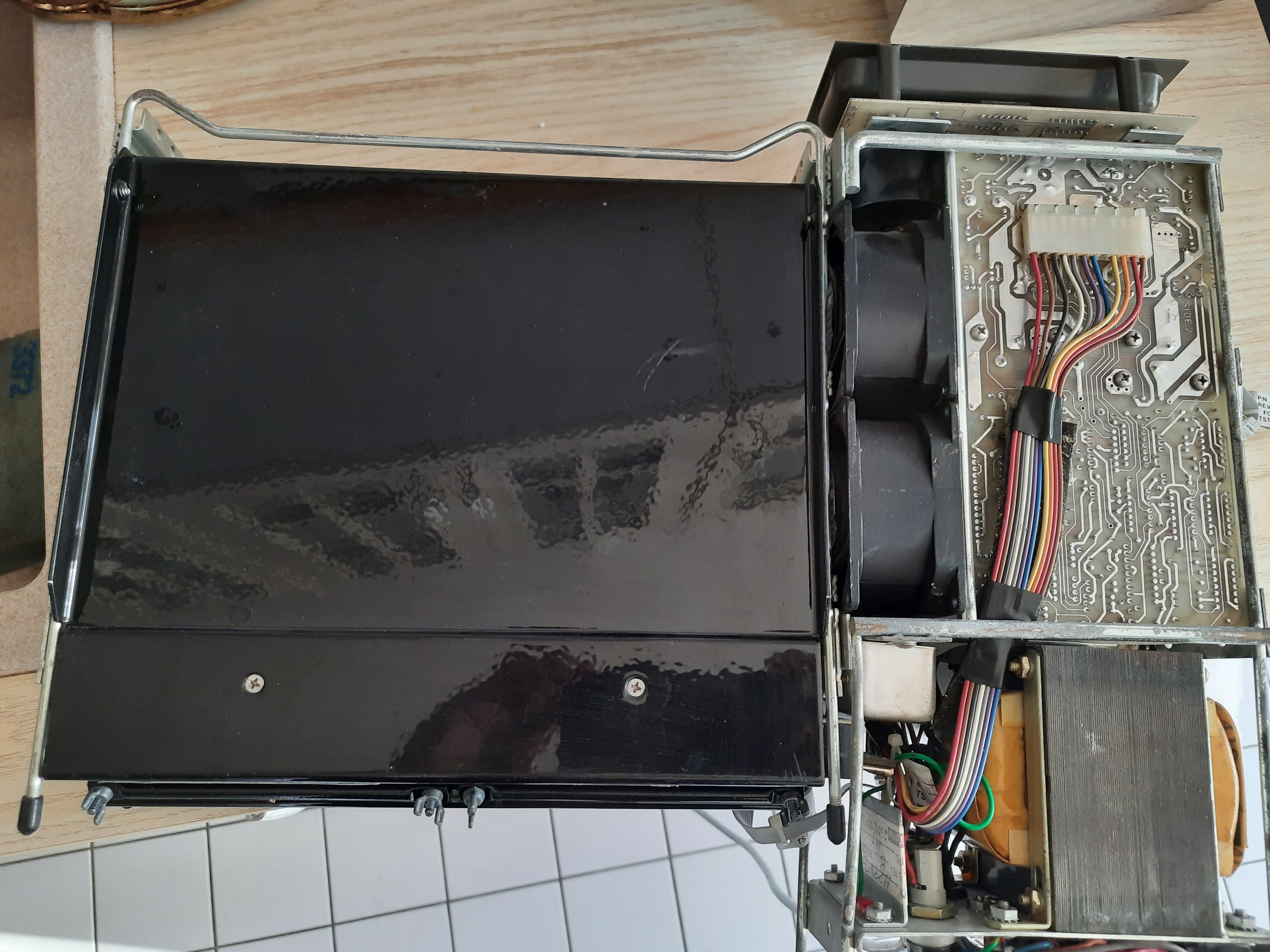
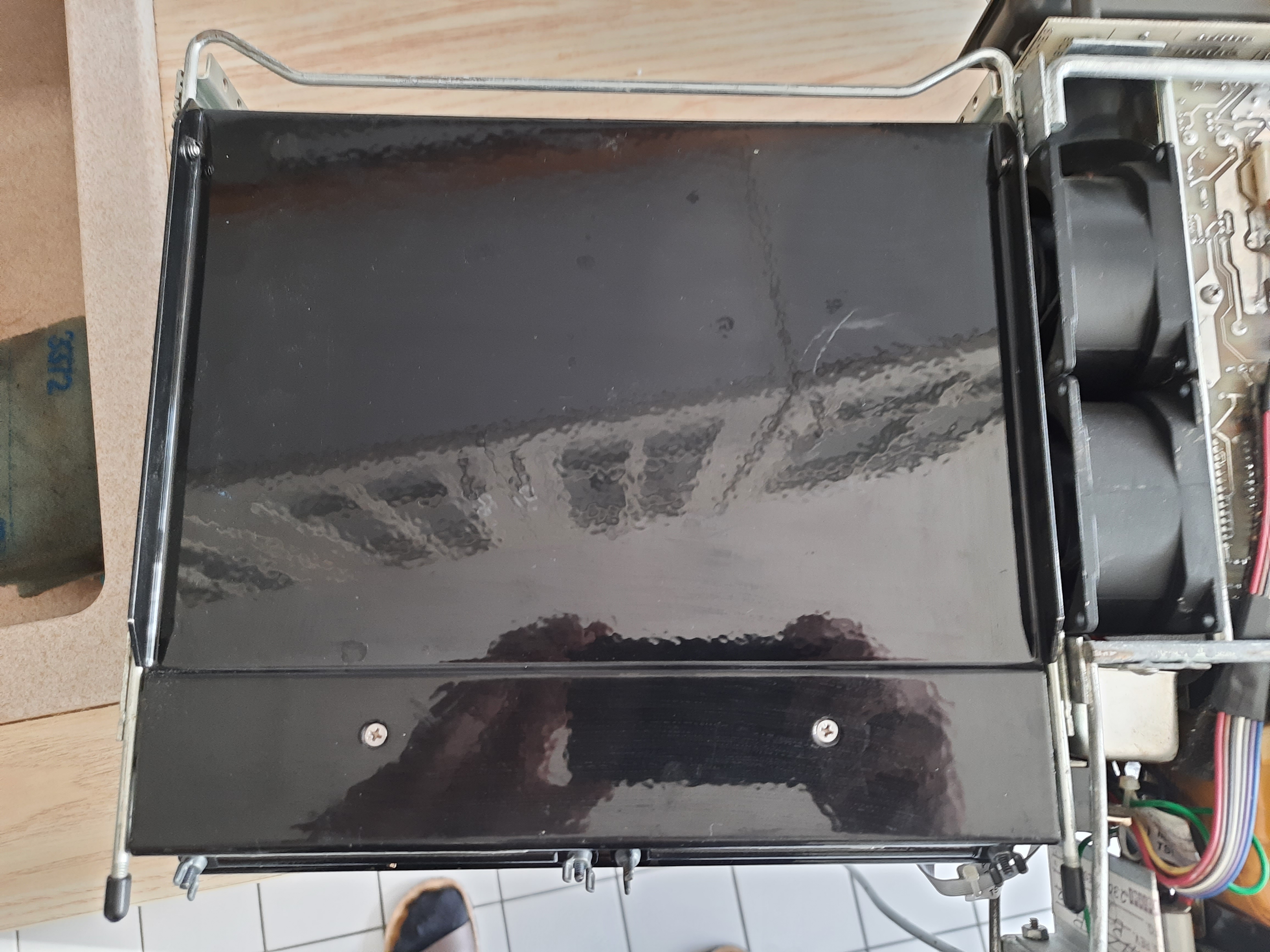
View from bottom side
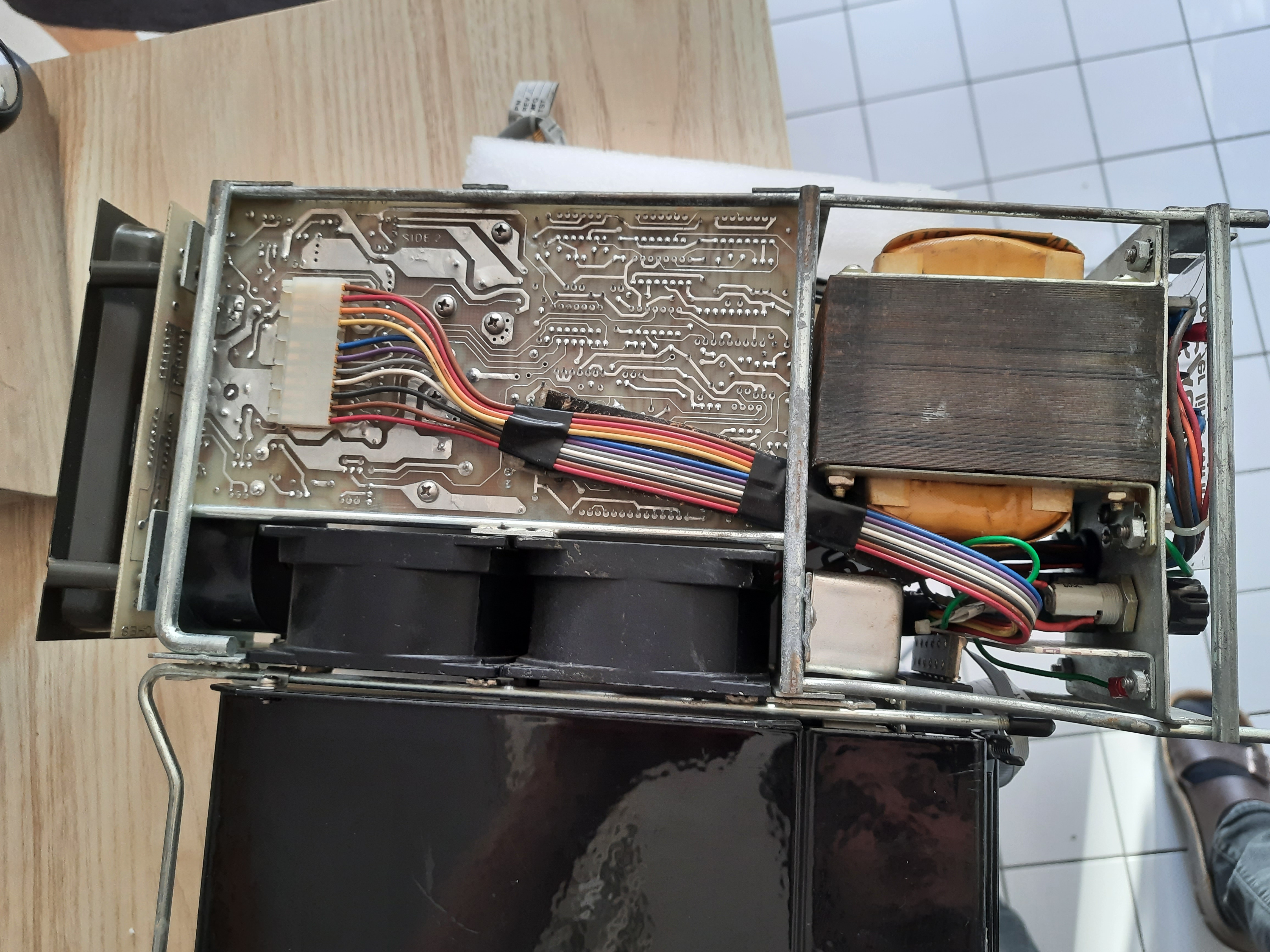
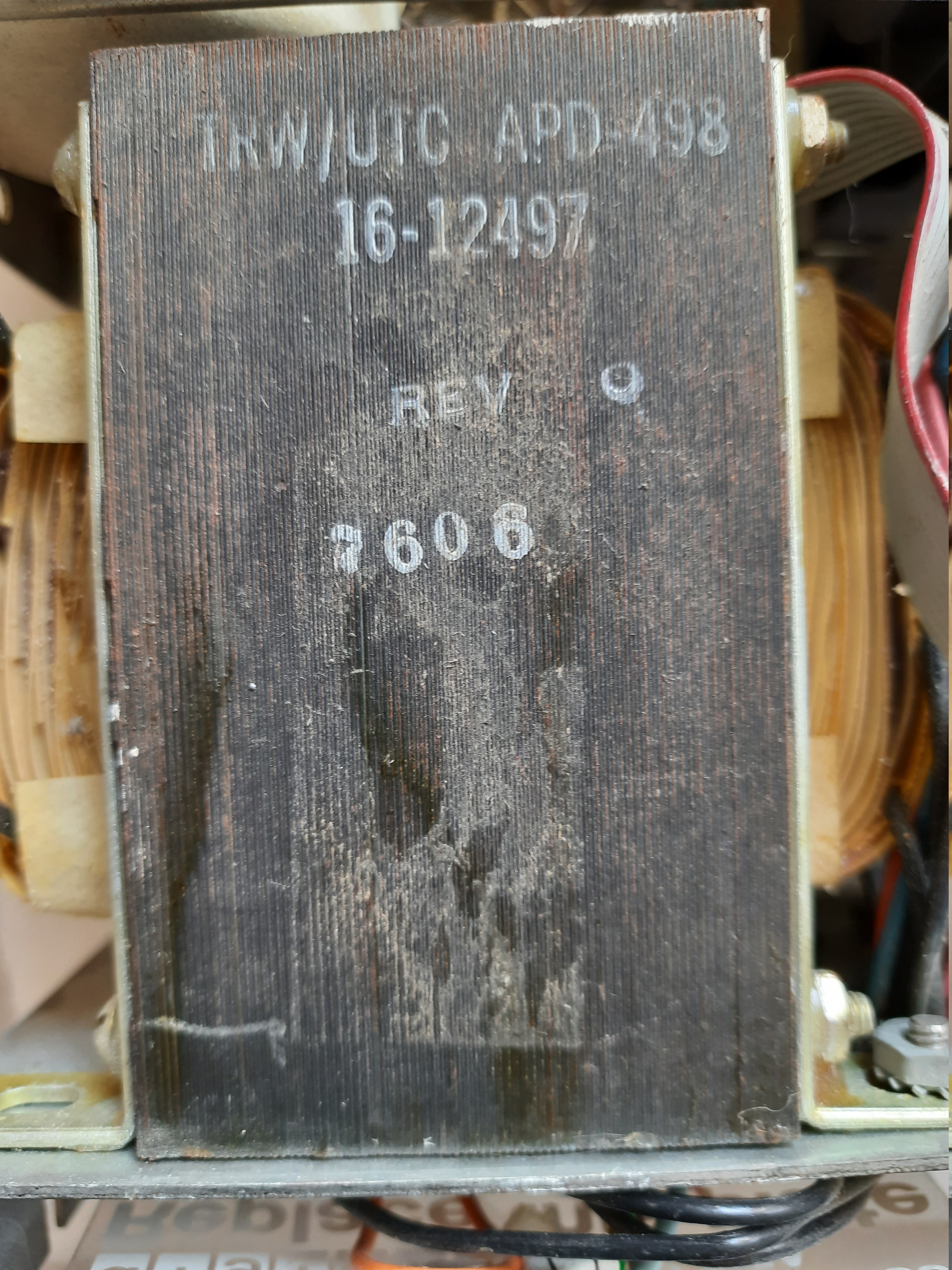
Power transformer
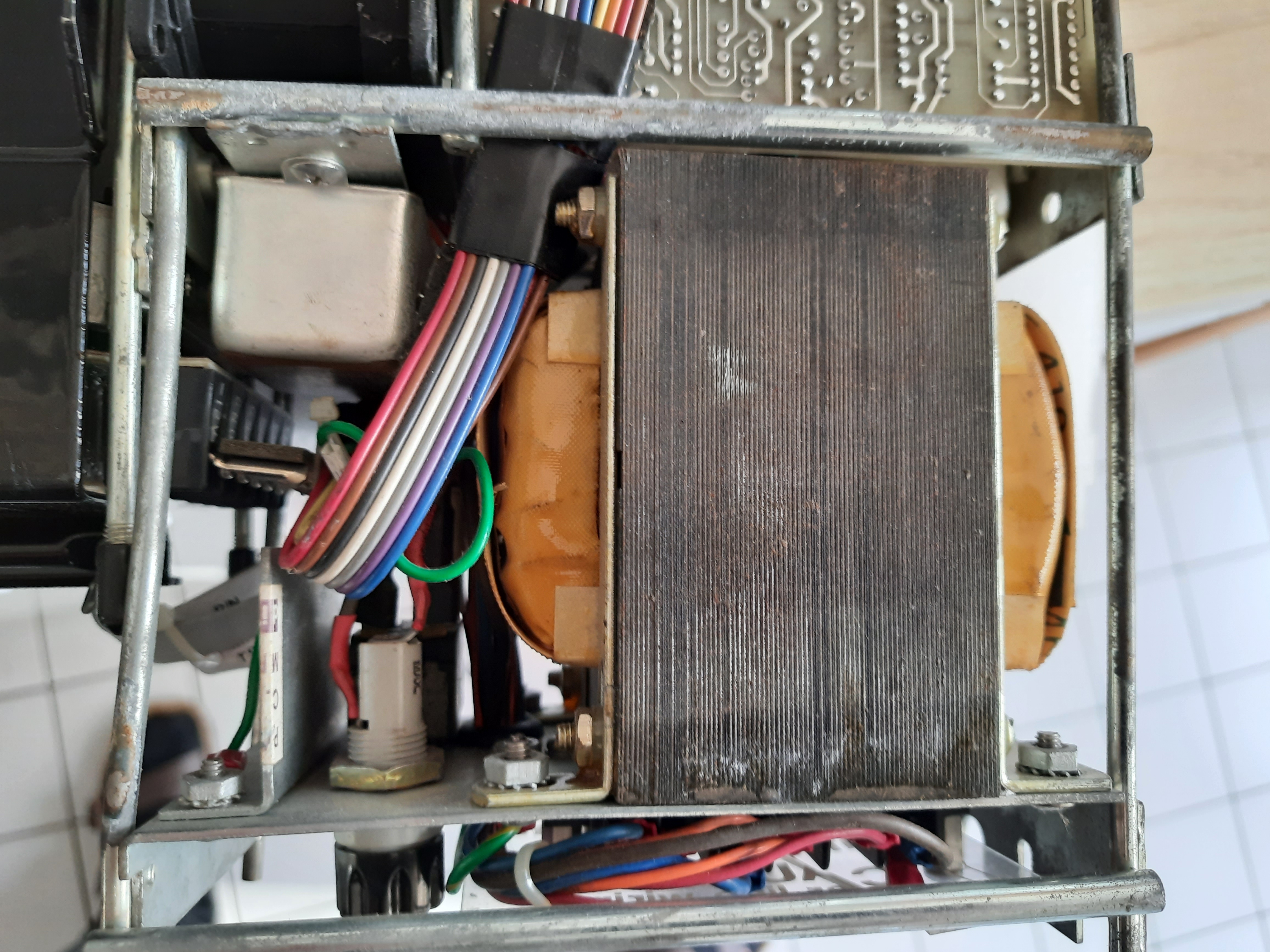
PSU board. The large white Cap is a 19000µF, 40 V type.
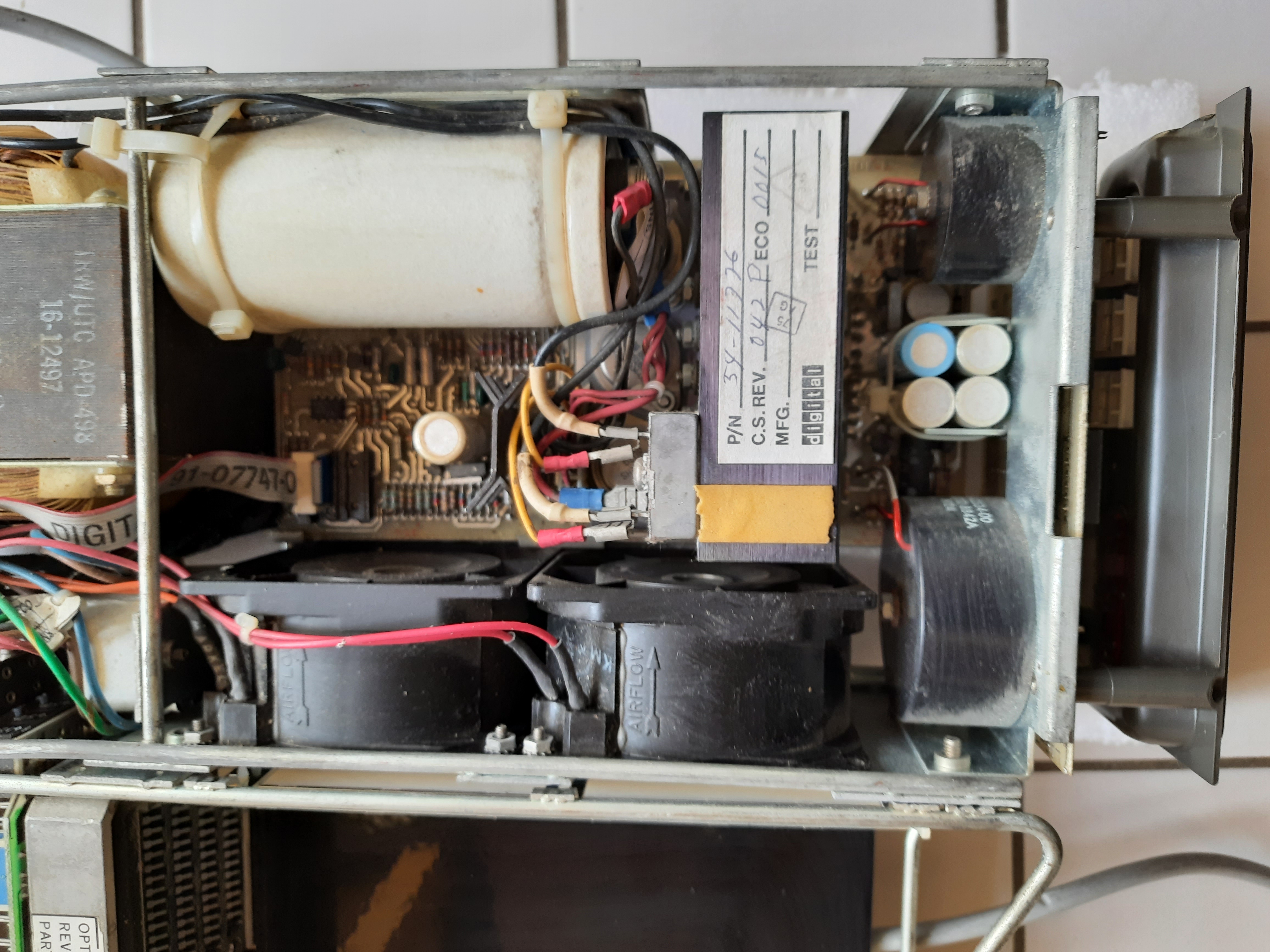
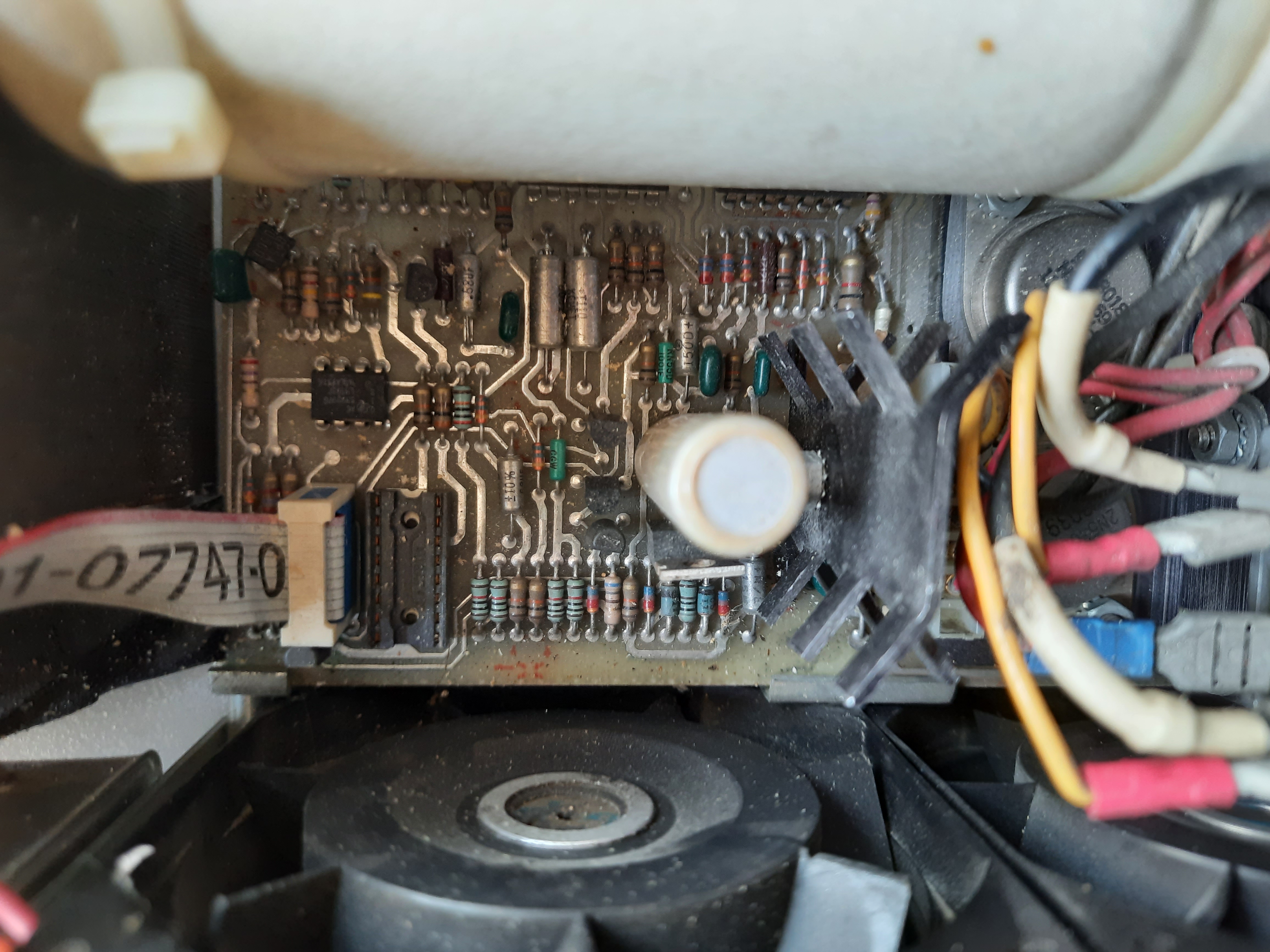
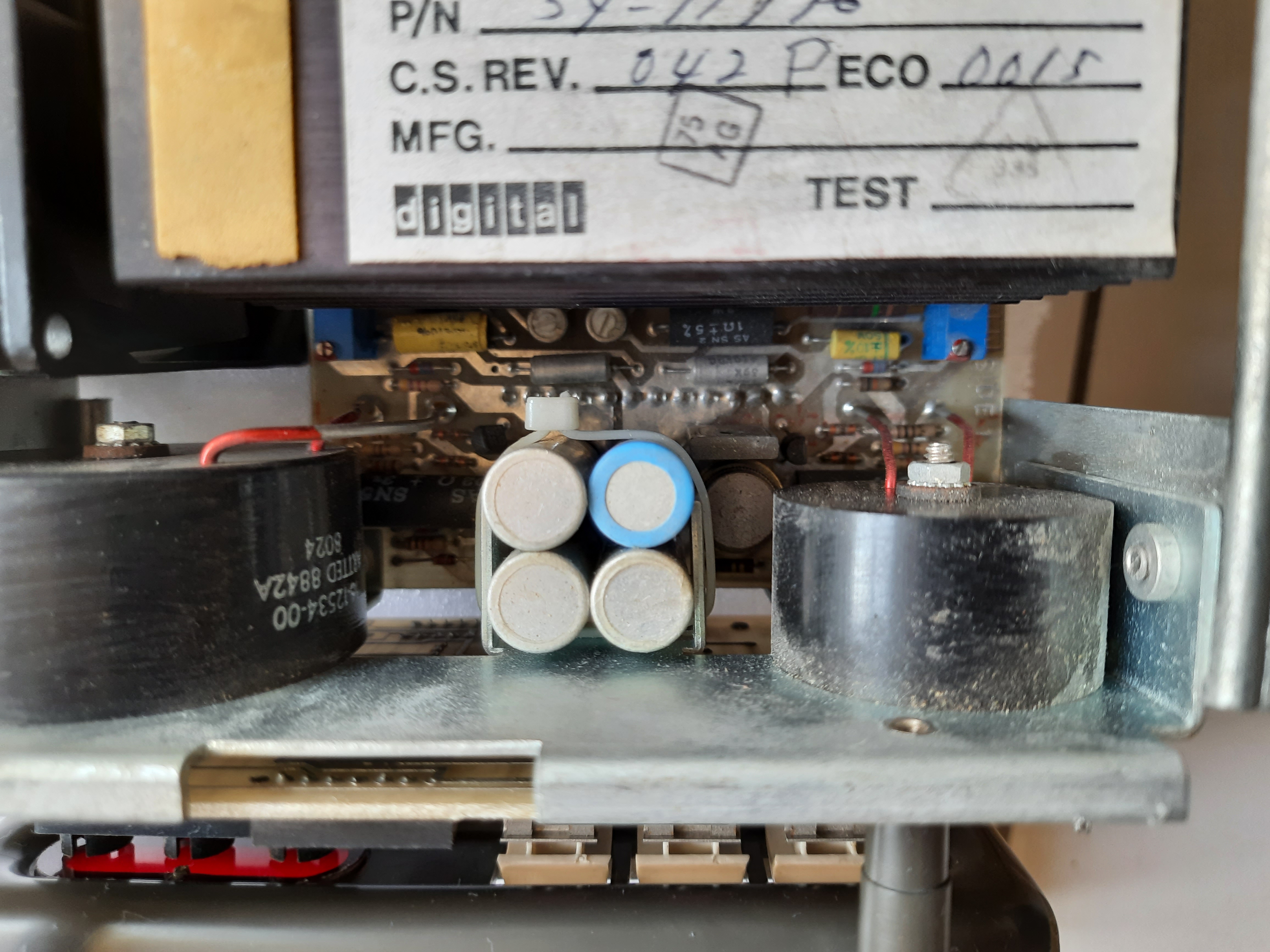
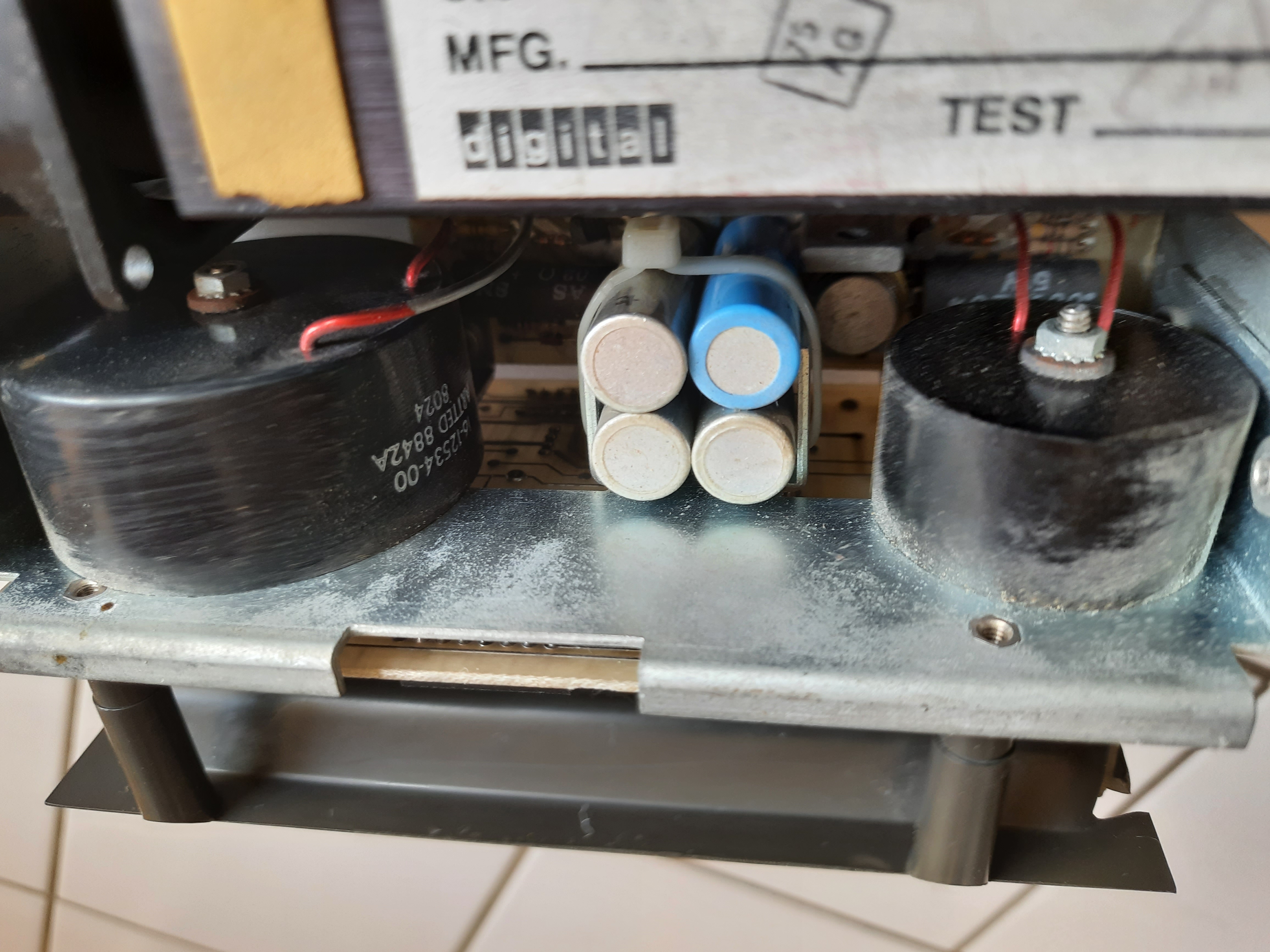
Two large inductors
Line cabling
H780 issues
When switching on the H780, I found that it provides about 24 volts at the big capacitor. From this some helper voltages (12 and 5 volts and others) are created and I found them ok.
So the transformer and everything up to the capacitor is ok.
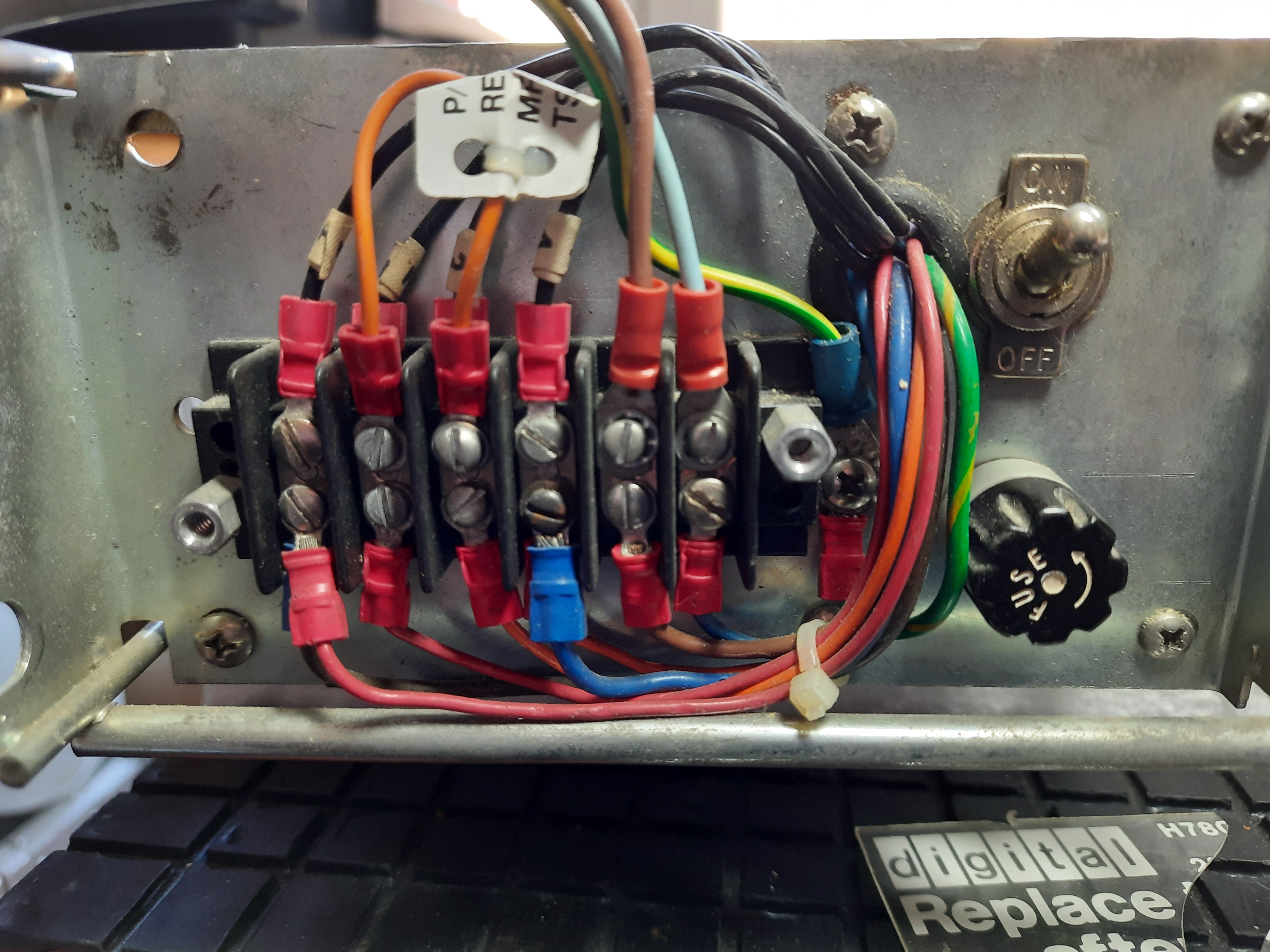
But there was nothing at power connector, going to the BA11-M. After studying the scheme, I checked the soldered fuses F1 and F2 for +5 and +12 volts. They are both broken.
This can have two reasons: the PSU is broken in itself or someone has shortcuted the output. I tried with some temporary replacements for both fuses and found that the PSU still delivers +5 volts and +12 volts, only fuses were defective.
The switching power supply is build very nicely by Digital. There is a line transformer creating save +24 volts. From this level, two independent schemes create +12 and +5 volts. So the PSU is relatively “safe” for someone searching for issues. The PSU also offers a simple crowbar circuit, which would break the fuses if for some reason over voltage would occur.
I have ordered replacement fuses (should: 5A and 2.5A, have ordered 5A and 3A). I will solder them on the solder side of PCBs to make replacement easy. To replace them on other side, I would need to get out the board from its cage, which looks complicated.
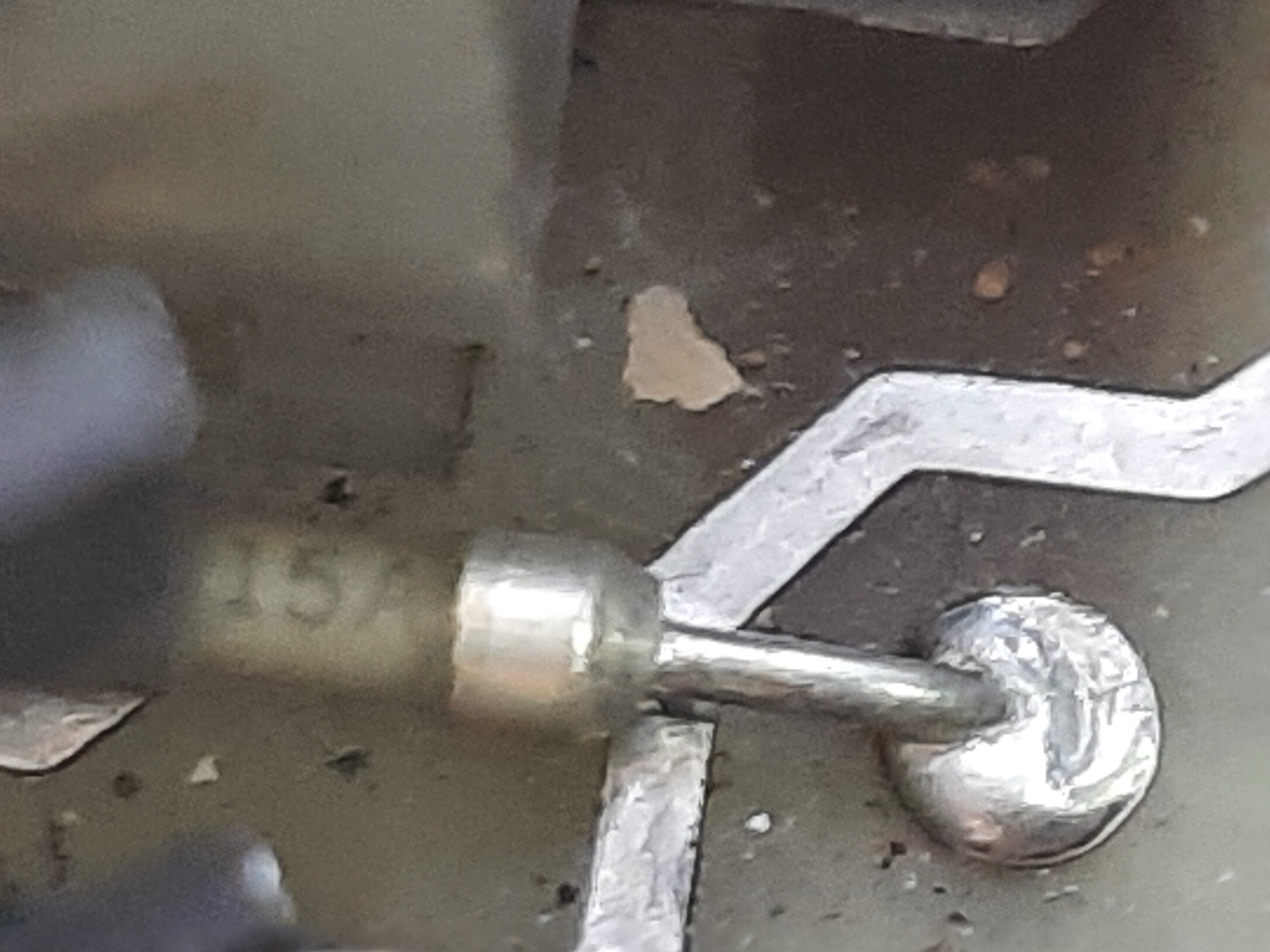
For unknown reason, the original fuses have this on them “5A” and “15A”. Strange.
5 Ampere fuse for +5V, it is the upmost left small device, white color
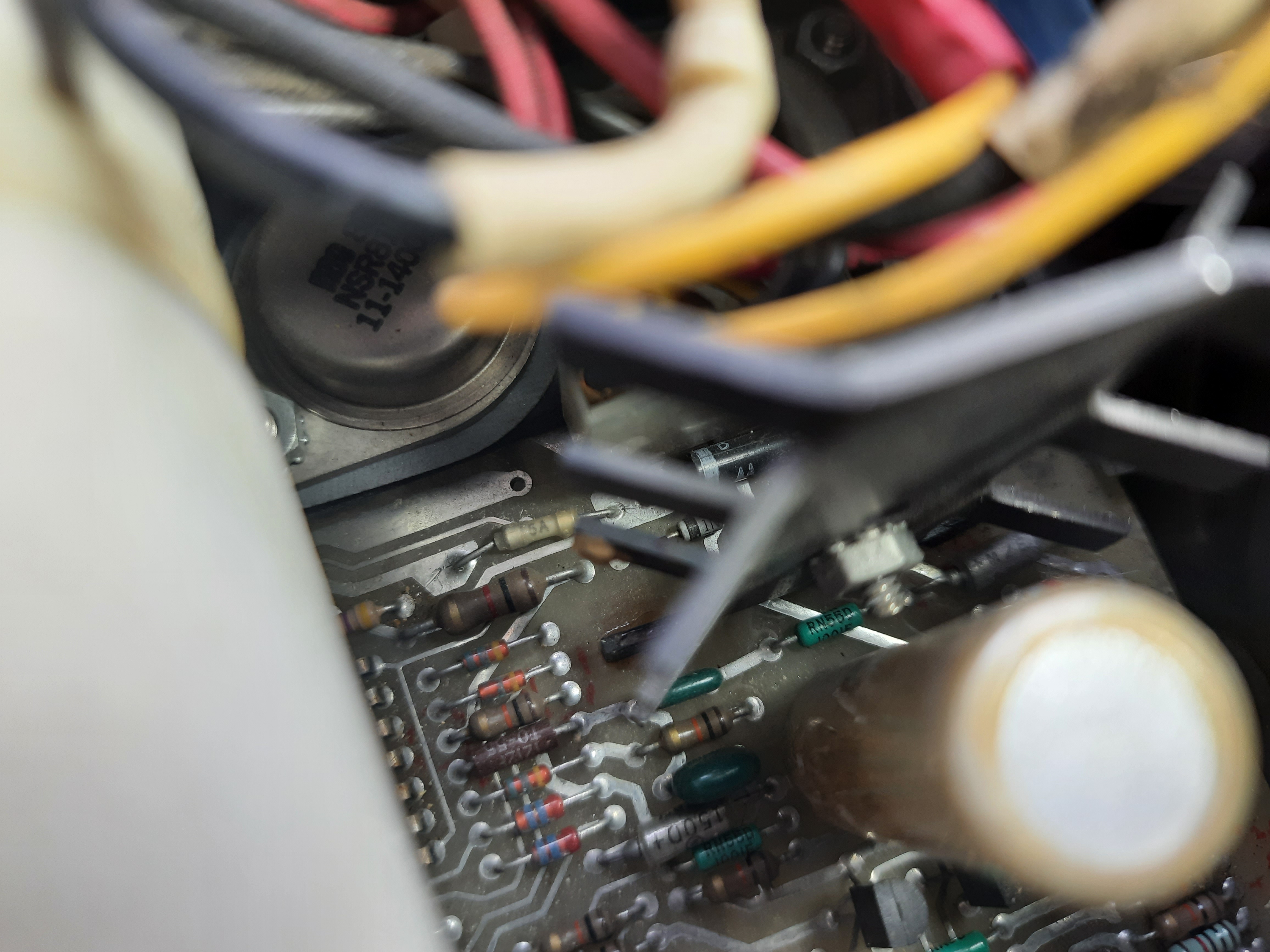
2.5 Ampere fuse for +12V. I don’t know why “15A” is printed on the fuse.
The soldering looks like 100% original.
Using a PC Power Supply for testing
Because of the loud H780 PSU, I replaced this for testing with a standard ATX PSU. The ATX offers only 10 amp at +5V, 17 amp at 12 volts, but for testing this will be enough.
The Control and Lamps panel connected to the H780 was replaced by a simpler solution. This solution is well described by http://www.diane-neisius.de/pdp11/ and http://avitech.com.au/?page_id=1657 . Both solutions differ a little bit and I have set up a third one, differing again. The later solution uses Open Collector outputs which is required by DEC manual. The first solution is made with less parts.
CPU Board M8186 went defective
When playing around with the machine, suddenly the board did not respond anymore. It broke for unknown reason, while using ODT.
The error was that the board did not respond to any input. On boot,
it only creates two characters LF STX, not the known character sequence
CR LF 000000 CR LF @
I did not find infos on how to troubleshoot a broken board. What I did:
- The CPU was exchanged with a working one. Same error.
- Measured output of quarz oscillator (13,824 Mhz) at W1 jumper. Was ok. I compared waveform with a working board.
- Measured
K2 CHIP CLK,TTL CLKandMCLK. They were all about 3 Mhz (roughly checked with scope) and looked ok. - There are 4 elkos on the board. I measured their voltages, which were the same as on a working board.
- With an Ohm-Meter, I’ve checked all passive parts on the board and compared with working board. This includes capacitors, resistors, diodes and a transistor. All looked well.
Hm. This can become a hard task. Because I have a working board, I will not continue troubleshooting for now.
Going further
In another document I have described my try to set up a minimal working system from the PDP parts I own.
Documents
LSI-11 PDP 11/03 User’s Manual
