This text is a 1:1 copy from
https://git.sr.ht/~adlpr/bk0010-01-programming/tree/main/item/bk0010-01-programming.md
To be sure to have it in the future, I keep it locally. All credits go to original authors of this document and its parts.
Electronika BK-0010-01 Programming Reference
Overview and basic operation
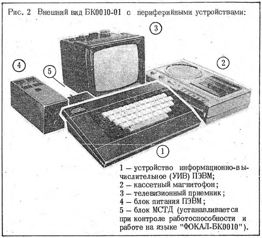
The Электроника БК-0010-01 / Electronika BK-0010-01 (hereafter “BK”) is a Soviet microcomputer intended for home and school use. It was manufactured from 1984 to c. 1993.
A BK enthusiast is known as a BeKashnik (БэКашник). 😎
Internals
BK hardware follows the Q-Bus scheme; all devices (CPU, memory, and I/O) are connected to a common bus through which control signals and data are transmitted.
-
CPU: К1801ВМ1; 16-bit architecture, binary-compatible with the PDP/LSI-11 instruction set (1 , 2), plus extended instructions
XORandSOB(noMUL,DIV,ASH). 3 MHz clock, with e.g. register transfer operations requiring a minimum of 12 cycles, so a few hundred k op/s. -
RAM: 32 KiB = 16 x КР565РУ6.
-
0.5K reserved for system variables and stack
-
15.5K free for programming; can be increased to 27.5K (“режим расширенной памяти (РП)”/“expanded-memory mode”), overwriting first 12K of graphics framebuffer RAM
-
16K (4K in expanded-memory mode) hardware-scrollable framebuffer; two graphics modes:
-
256x256, 32 chr/line, 2-bit color (red, green, blue, black)
-
512x256, 64 chr/line, 1-bit color (white/black)
-
-
-
ROM: 32 KiB = 4 x КР1801РЕ2.
-
The first 8K contains MONITOR (МОНИТОР), the BK’s OS. It includes the keyboard driver, screen driver, tape recorder driver, and an 8x10 font.
-
In the 0010-01 model, the other three ICs contain a Vilnius BASIC 1986.07.24 interpreter.
-
With the MSTD cartridge connected, the upper part of the address space is remapped to that of the original model BK-0010: a FOCAL interpreter and a diagnostic test suite (and 8K of empty space where you could maybe connect another IC??).
-
For a very long time it was believed that BK-0010, unlike most home microcomputers, had no Western counterpart or prototype. Lately I’ve learned that BK-0010 looks very much like a trimmed Terak 8510/a. I am adapting my BK-0010/11 emulator to emulate Terak as well, using whatever documentation is available on BitSavers.
Keyboard
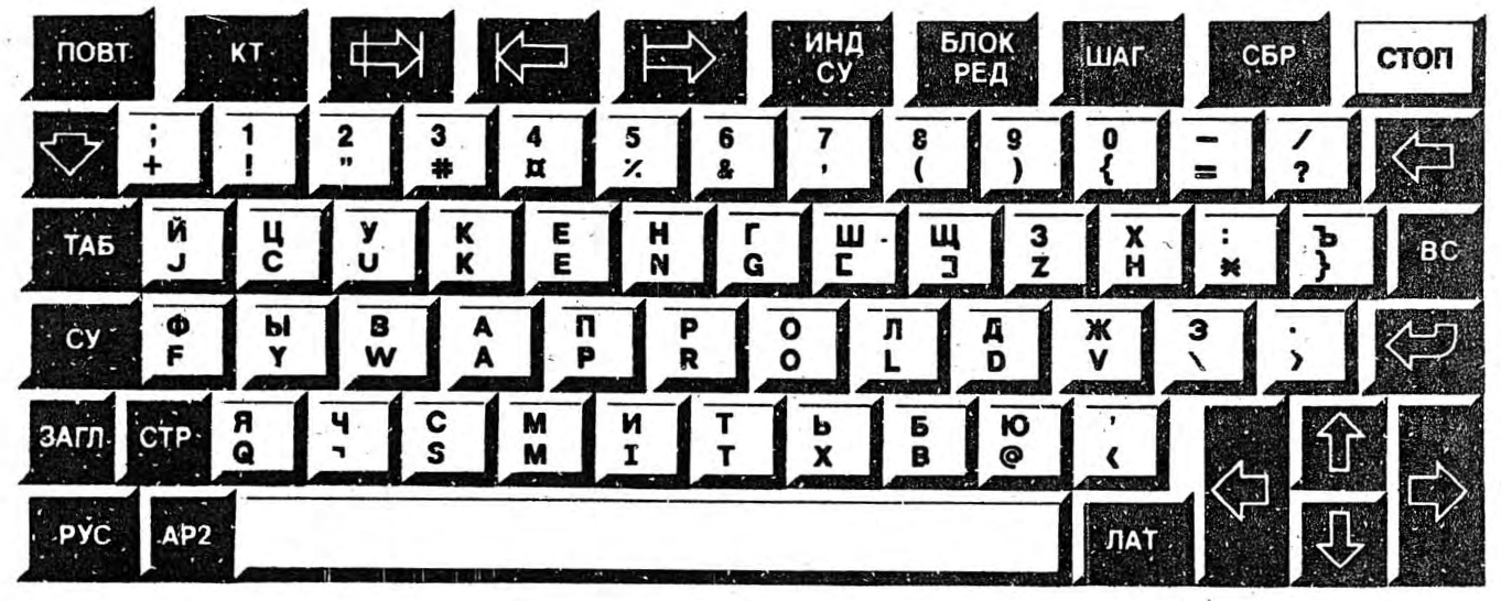
Function key descriptions, left to right, top to bottom:
| Key | Desc (ru) | Name (en) | Function |
|---|---|---|---|
[ПОВТ] |
повтор | Repeat | Repeat last key pressed |
[КТ] |
Конец Текста | End-of-text | Discard input line |
[⇸∣] |
удаление правой от курсора части строки | Delete Line (?) | Delete line right of cursor |
[⇤] |
сдвижка в строке | Delete | Delete character at cursor, shift line right of cursor one character left |
[⇰] |
раздвижка в строке | Insert | Insert space at cursor, shift line right of cursor one character right |
[ИНД СУ] |
Индикация Символов Управляющих | Indicate Control Characters | Toggle control character display (as inverted letters) |
[БЛОК РЕД] |
блокировка редактирования | Edit Lock | Disables cursor keys |
[ШАГ] |
пошаговое | Step | Step-by-step execution for BASIC |
[СБР] |
сброс | Form feed | Clear the display |
[СТОП] |
стоп | Stop | Halt execution |
[⇩] |
нижний регистр | Shift | Use to input secondary characters on lower row of keys. In Russian (Cyrillic) + uppercase input mode, inputs lowercase. |
[⇦] |
забой | Backspace | Delete character left of cursor |
[ТАБ] |
таб | Tab | Tab |
[ВС] |
Возврат Строки | Return String | Recall the last line to be edited |
[СУ] |
Символ Управляющий | Control Character | Use with letter keys to input control characters (= letter code - 100) |
[↩] |
ВВОД/ВК (Возврат Каретки) | Enter/Return | Enter/Carriage Return |
[ЗАГЛ] |
заглавный | Uppercase | Set input to uppercase |
[СТР] |
строчный | Lowercase | Set input to lowercase |
[РУС] |
русский | Russian | Set input to Russian (Cyrillic) |
[АР2] |
второй символ управляющий | Secondary Control Character | Use with letter keys to input control characters (= letter code + 100) |
[ЛАТ] |
латинский | Latin | Set input to Latin |
[⭠]``[⭢]``[⭡]``[⭣] |
клавиши со стрелками | Arrow keys | Move the cursor |
| Key combination | Function |
|---|---|
[СУ]+[@] |
Pause the display |
[СУ]+[G] |
␇ (Bell) |
[СУ]+[M] |
Set tab stop |
[СУ]+[P] |
Reset tab position |
[СУ]+[R] |
Initial cursor setting |
[СУ]+[T] |
Move cursor 8 positions to the right |
[СУ]+[U] |
Move cursor to the beginning of the next line |
[СУ]+[]] |
Up-right arrow(??) |
[СУ]+[}] |
Down-left arrow (??) |
[СУ]+[\] |
Up-left arrow (??) |
[СУ]+[¬] |
Down-right arrow (??) |
[АР2]+[-] |
Toggle screen inversion |
[АР2]+[,] |
Toggle character inversion |
[АР2]+[;] |
Toggle 32- / 64-character mode |
[АР2]+[:] |
Toggle cursor display |
[АР2]+[.] |
Setting the current operating modes of the screen in the service line (???) |
[АР2]+[/] |
Toggle underline |
[АР2]+[⇦] |
Switch the line editing mode in FOCAL |
[АР2]+[СБР] |
Toggle expanded-memory mode |
[АР2]+[1] |
Keyboard macro K1 (BASIC default: COLOR ) |
[АР2]+[2] |
Keyboard macro K2 (BASIC default: AUTO ) |
[АР2]+[3] |
Keyboard macro K3 (BASIC default: GOTO ) |
[АР2]+[4] |
Keyboard macro K4 (BASIC default: LIST ) |
[АР2]+[5] |
Keyboard macro K5 (BASIC default: RUN↩) |
[АР2]+[6] |
Keyboard macro K6 (BASIC default: COLOR 1,0↩) |
[АР2]+[7] |
Keyboard macro K7 (BASIC default: CLOAD") |
[АР2]+[8] |
Keyboard macro K8 (BASIC default: CONT↩) |
[АР2]+[9] |
Keyboard macro K9 (BASIC default: .↩) |
[АР2]+[0] |
Keyboard macro K10 (BASIC default: CLS↩RUN↩) |
[АР2]+[⇩]+[1] |
Set input color to red () |
[АР2]+[⇩]+[2] |
Set input color to green () |
[АР2]+[⇩]+[3] |
Set input color to blue () |
[АР2]+[⇩]+[4] |
Set input color to black () |
[АР2]+[⇩]+[5] |
Toggle GRAPH (ГРАФ) graphics-drawing mode |
[АР2]+[⇩]+[6] |
Within GRAPH, toggle REC (ЗАП) mode |
[АР2]+[⇩]+[7] |
Within GRAPH, toggle DEL (СТИР) mode |
Display
Display output consists of 25 lines of 8x10px characters, the first and topmost being a “service line” with information about current keyboard and screen operating modes.
There are two display modes, toggled by [АР2]+[;]:
-
32 characters per line: 256x256 2-bit color (black, red, green, blue);
-
64 characters per line: 512x256 1-bit color (black and white)
Graphics drawing (ГРАФ) mode
The key combination [АР2]+[⇩]+[5] toggles between text entry and direct
graphics-drawing mode. On entering graphics mode, ГРАФ (for “графика”) will
display on the service line, and the cursor will change to crosshairs, which can
be moved pixel-by-pixel with the arrow keys.
Entering a decimal number followed by an arrow key will move the cursor that
many pixels; e.g., [1][0][0][⭢] will move 100px to the right. Any non-digit
entered will cancel this process.
To begin drawing, press [АР2]+[⇩]+[5]. ЗАП (“запись”) will display on
the service line. Any pixel the cursor touches will be changed to the current
color.
To erase previously drawn pixels to the background color, toggle [АР2]+[⇩]
+[7] for СТИР (“стирание”) mode. Any pixel the cursor touches will be
erased.
Edit Lock (БЛР) mode
The [БЛОК РЕД] key activates edit-lock mode (БЛР on the service line). Keys
and input combinations that control editing will instead be inputted as visible
textual characters, presumably facilitating the preparation of data sequences
for programming, I guess.
Ports
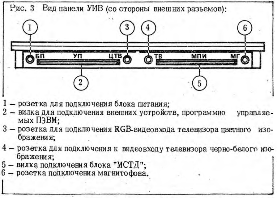
Facing back of unit, from left to right:
| Abbr | Name (ru) | Description |
|---|---|---|
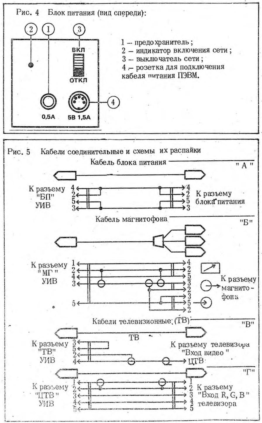
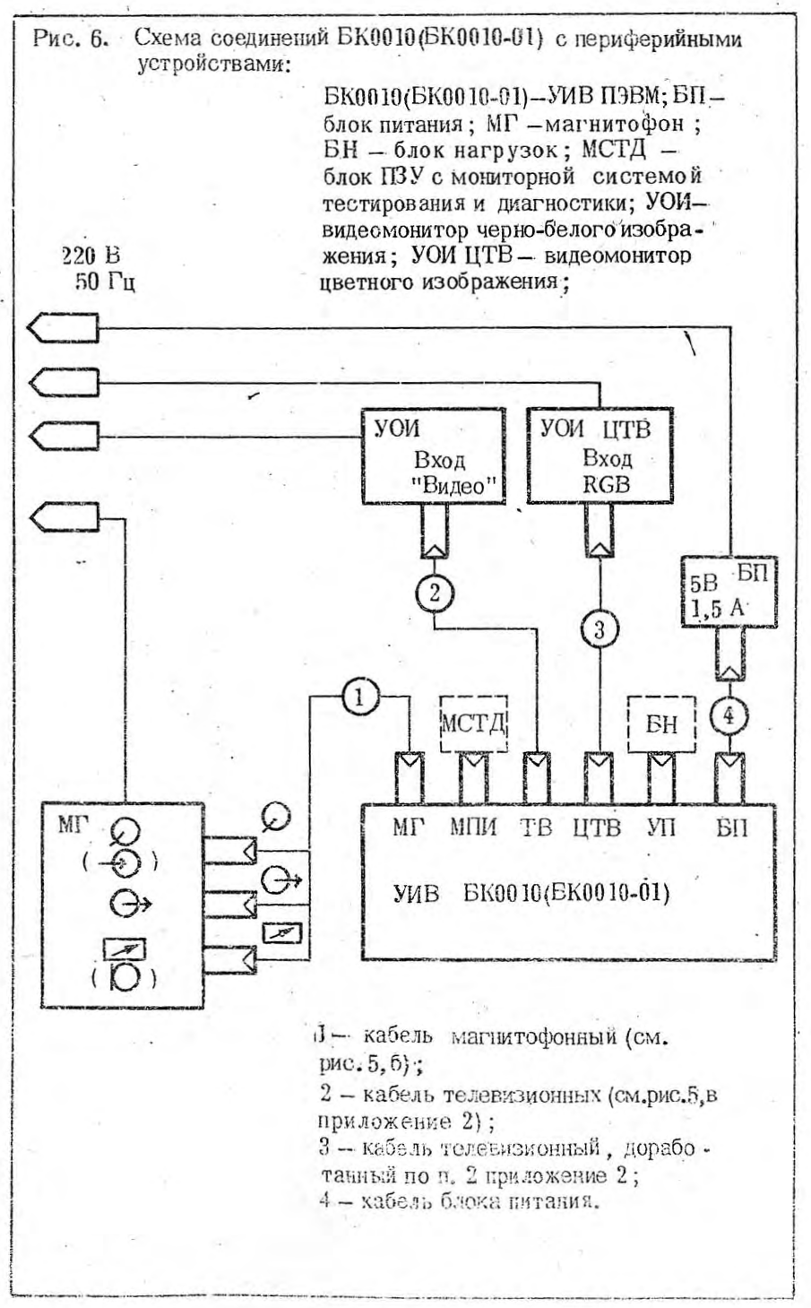
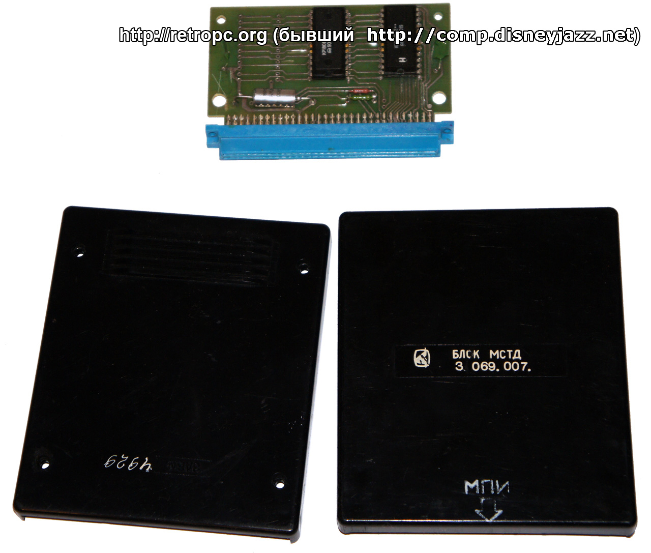
| БП | Блок Питания | 5V 1.5A power supply; 5-pin DIN |
| УП | Устройство Периферийное | Parallel port; СНП 58-64>There was a provision (two otherwise unused pins on the parallel port, on some production runs - two points on the motherboard) and some BIOS code) for a software-driven TTL-level serial connection [ИРПС (IRPS) protocol] with speeds up to 9600 baud [this seems to have been used with the 0010Ш model where it could be interfaced with via registers &17656x?] |
| ЦТВ | Цветной Телевизор | Color video output (@@@@ ПЭВМ format, whatever that is); 5-pin DIN |
| ТВ | Телевизор | Monochrome video output; 5-pin DIN |
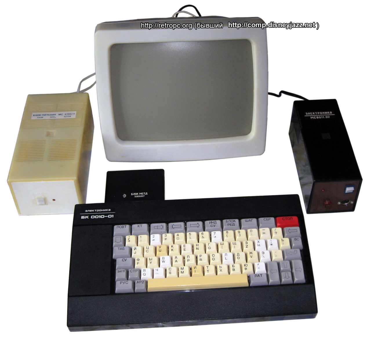
| МПИ | ? МСТД подключения … ???? | MSTD (original model ROM) cartridge slot; СНП 58-64 |
| МГ | Магнитофон | Tape recorder I/O (“encoding used is approx. 1200 bits/s, not very efficient or reliable (pulse width modulation with a strobe after every bit)”); 5-pin DIN |
Common expansions
-
блок МСТД (Мониторная Система Тестовой Диагностики, Monitor System Test Diagnostics / MSTD cartridge): contains ROM for original model BK-0010 (FOCAL interpreter and test suite/debugger)
-
блок нагрузок ( load [?] cartridge): tests operability of the parallel port, used in conjunction with the MSTD cart
-
блок КНГМД ( KNGMD [?] cartridge): connect to 5.25" floppy drive
-
блок КМ ( KM [?] cartridge): connect a printer and mouse. e.g. УВК-01 Марсианка , Электроника МС-6312
-
блок Менестрель ( Minstrel cartridge): sound card with 2 channels, 9-10? octave range, effects: legato, vibrato, glissando, smooth tempo change
MSTD test suite and debugger
@@@@@@@@@@ note: I don’t have the MSTD cart so I can’t test any of this
The test system on the MSTD card includes a set of tests to check the health of the BK, and a remote debugger that allows you to view and modify memory contents directly.
To work with the test system, connect the MSTD cartridge and use the P T
command to switch from FOCAL to the test system.
The test system command prompt is indicated by the + sign.
Digits 1 to 5 are the commands to run tests of: RAM and ROM, keyboard
performance (designed for the earlier model BK-0010 keyboard), the parallel
port, the character generator/image quality (?), and tape recorder operation.
To exit the test system to FOCAL, press К.
To switch to the console debugger, enter Cyrillic input mode (РУС key) and
type ТС.
The debugger command prompt is indicated by the ¤ symbol. The debugger allows
you to view and modify the contents of memory, as well as perform a number of
operations with memory ranges. Key concepts are the current address (А) and *
array length* (Д), together specifying a consecutive block of memory [А, А+Д).
All addresses and values should be specified in octal.
| Command | Description |
|---|---|
А |
check value of current address |
{value}А |
set current address to {value} |
Д |
check value of array length |
{length}Д |
set array length to {length} |
{value}Р |
write {value} to each address in current array |
{address}С |
compare current array and [{address}, {address}+Д) |
Х |
calculate checksum of current array |
{address}П |
copy and overwrite (переписать) current array starting from address {address} |
{length}Л |
dump memory [А, А+{length}) |
И |
read word [А] |
{value}И |
load word {value} to [А] |
Б |
read byte [А] |
{value}Б |
load byte {value} to [А] |
Ц |
cyclic (циклическое) read-write [А] (????) |
Щ |
unprotect the system RAM area (addresses <&001000) |
, |
read word [А] and inc А |
{value}, |
load word {value} to [А] and inc А by 2 |
. |
read byte [А] and inc А |
- |
read word [А] and dec А by 2 |
: |
read byte [А] and dec А |
МЧ, МЗ, МФ |
read (чтение), write (запись), search for file (поиск файла) on tape (магнитофон) |
{address}G |
start program from {address} |
К |
exit to FOCAL |
Memory map
By convention with this architecture, memory addresses are written in **
octal** (&xxxxxx).
| Start address | End address | Size | Content |
|---|---|---|---|
&000000 |
&000777 |
0.5K | System variables and stack |
&001000 |
&037777 / &067777 (EMM) |
15.5K / 27.5K (EMM) | User RAM |
&040000 / &070000 (EMM) |
&077777 |
16K / 4K (EMM) | Screen RAM |
&100000 |
&117777 |
8K | System ROM (MONITOR and drivers) |
&120000 |
&177577 |
23.875K | BASIC |
&177600 |
&177777 |
128 B | Registers |
System variables (&000000–&000777)
Interrupt vectors
| Vector Address | Source | Type |
|---|---|---|
&000004 |
access on an odd-numbered (i.e. non-word-aligned) or invalid address; [СТОП] (STOP) key / HALT instruction |
HW / SW |
&000010 |
invalid opcode | SW |
&000014 |
PSW T flag + BPT (breakpoint trap i.e. debug interrupt) |
SW |
&000020 |
IOT (software I/O interrupt) |
SW |
&000024 |
power failure (?) | HW |
&000030 |
EMT (emulator traps i.e. system subroutines) |
SW |
&000034 |
TRAP (executing-system subroutines e.g. BASIC/FOCAL) |
SW |
&000060 |
keyboard | HW |
&000100 |
external timer (parallel port) | HW |
&000274 |
keyboard with [АР2] pressed |
HW |
&000360 |
ИРПС (parallel port serial line) receive | HW |
&000364 |
ИРПС (parallel port serial line) send | HW |
Note that despite the existence of a clock register, there is no clock interrupt.
System variables
| Address | Len (B) | Description |
|---|---|---|
| ** | ||
| DMBK [?]** | ||
| &040 | 1 | 32/64 mode ( 0 - " 64 " mode, 377 - " 32 " mode) |
| &041 | 1 | Screen inversion ( 0 - off, 377 - on) |
| &042 | 1 | Extended memory mode ( 0 - off, 377 - on) |
| &043 | 1 | Register ( 0 - LAT, 200 - RUS) |
| &044 | 1 | Underline ( 0 - off, 377 - on) |
| &045 | 1 | Character inversion ( 0 - off, 377 - on) |
| &046 | 1 | ИСУ (ISU) mode ( 0 - off, 377 - on) |
| &047 | 1 | БЛР (BLR) mode ( 0 - off, 377 - on) |
| &050 | 1 | ГРАФ (GRAF) mode ( 0 - off, 377 - on) |
| &051 | 1 | ЗАП (ZAP/REC?) mode ( 0 - off, 377 - on) |
| &052 | 1 | СТИР (STIR) mode ( 0 - off, 377 - on) |
| &053 | 1 | 32/64 mode in the service line ( 0 - " 64 “, 377 - " 32 “) |
| &054 | 1 | Underline in the service line ( 0- off, 377- on) |
| &055 | 1 | Inversion of service line ( 0 - off, 377 - on) |
| &056 | 1 | Cursor blanking ( 0 - off, 377 - on) |
| **Keyboard driver | ||
| variables** | ||
| &104 | 1 | Keyboard buffer |
| &105 | 1 | Sign of writing code to the buffer |
| &106 | 2 | Repeat constant buffer |
| &110 | 1 | Code Repeat Sign |
| &111 | 1 | Tab counter |
| &112 | 10 | Tab Positions (bitwise in 64-character mode) |
| &122 | 1 | Key counter |
| &124 | 2 | Current key address |
| &126 | 2 | Keyboard macro K10 string pointer |
| &130 | 2 | Keyboard macro K1 string pointer |
| &132 | 2 | Keyboard macro K2 string pointer |
| &134 | 2 | Keyboard macro K3 string pointer |
| &136 | 2 | Keyboard macro K4 string pointer |
| &140 | 2 | Keyboard macro K5 string pointer |
| &142 | 2 | Keyboard macro K6 string pointer |
| &144 | 2 | Keyboard macro K7 string pointer |
| &146 | 2 | Keyboard macro K8 string pointer |
| &150 | 2 | Keyboard macro K9 string pointer |
| **Display driver | ||
| variables** | ||
| 152 | 1 | Sign of roll violation |
| 153 | 1 | Sign of recording a point in ГРАФ mode ( 0 - СТИР, 1 - ЗАП) |
| 154 | 1 | Graphic point position mask (GT) [графической точки (ГТ)] |
| 155 | 1 | GT initial position mask |
| 156 | 2 | Character number on screen |
| 160 | 2 | Absolute cursor address in screen RAM |
| 162 | 2 | Character Length in Bytes |
| 164 | 2 | The length of the screen RAM in characters |
| 166 | 2 | GT address (number) on the screen |
| 170 | 2 | GT address |
| 172 | 2 | Graphic Vector Length |
| 174 | 2 | TV line counter |
| 176 | 2 | X coordinate of the last graphic point |
| 200 | 2 | Y coordinate of the last graphic point |
| 202 | 2 | Start address of screen RAM |
| 204 | 2 | Start address of the informational part of the screen minus 40000 |
| 206 | 2 | Screen RAM length in bytes |
| 210 | 2 | The length of the information part of the screen |
| 212 | 2 | Background color code on screen |
| 214 | 2 | character color code on screen |
| 216 | 2 | Background color code in the service line |
| 220 | 2 | character color code in service line |
| 222 | 2 | Key counter when entering from the keyboard |
| 224 | 2 | Counter setting indicators GRAP mode |
| **parallel port? system | ||
| variables** | ||
| 250 | 2 | Length 0 for tape driver |
| 252 | 2 | Length 1 for tape driver |
| 254 | 2 | parallel port bit length (????) |
| 256 | 2 | Copy of parallel port output register (&177714) |
| 260 | 2 | The address of the subroutine executed during interrupt on a vector of 60. If 0 , then nothing is done |
| 262 | 2 | If 0, then the code for Enter/Return is #&12, otherwise #&15 |
| 264 | 2 | Starting address of last downloaded (tape) program |
| 266 | 2 | Length of last downloaded program |
| **Tape driver | ||
| variables** | ||
| 300 | 1 | Sign of inverse signal |
| 301 | 1 | Error sign |
| 302 | 2 | Sign of fictitious reading |
| 304 | 2 | Array address increment |
| 306 | 2 | Parameter block address |
| 310 | 2 | Stack pointer buffer |
| 312 | 2 | Checksum buffer |
| 314 | 2 | Length limit 0 |
User RAM (&001000–&037777 or &067777)
Free for programming, but note that BASIC system variables are in &002000
–&003777 and should be free if you wish to utilize any of the BASIC
arithmetic subroutines (see below section).
@@@@@@@@ TODO: move instructions on how to set expanded-memory mode here
Screen RAM (&040000 or &070000–&077777)
&040000 : topmost, “service” line
one line = 64 (&100) B, one character line = 640 (&1200) B
…
System ROM
MONITOR (&100000–&117777)
Power-on initialization is handled by the BK’s OS, MONITOR (МОНИТОР). This
consists of setting the stack pointer, interrupt vectors, and other system
variables, after which the screen is cleared and control passes to
address &120000 . For the model BK-0010-01, this is the built-in BASIC
interpreter, or FOCAL on the MSTD cart.
You can switch back to MONITOR command mode (from BASIC: MO), typically
necessary for working with binary executables. Like BASIC commands, MONITOR
commands may be used in full or abbreviated.
| Command | Description | Parameter default |
|---|---|---|
M/М(АГ){address} |
download program from the tape recorder to {address}; prompts: “Имя?” (“Name?”, i.e. filename on tape to download) | address from the table of contents of the downloaded file |
L/Л(иния){address} |
load from {address} on line (ИРПС parallel port serial line??) | address from the table of contents of the downloaded file |
S/С(тарт){address} |
start program from {address} | last downloaded-to address (saved to &264 after either above command) |
P/П(уск) |
call program at &140000 |
|
T/T(ест) |
call program at &160100 (test system on МСТД cartridge) |
|
any letter A/А through K/К |
return control to &120000 (BASIC/FOCAL/etc.) |
BASIC (&120000–&177577)
The built-in interpreter is Vilnius BASIC 1986.07.24. Not gonna detail it all here, pretty typical implementation, though as Wikipedia notes:
The dialect was very close to MSX BASIC. The major differences were the lack of the
PLAY,SOUND,VPOKEandPUT SPRITEoperators, the inability to open several files at the same time, and the inability to use more than one operator on one line.
Note that the string postfix is ¤.
Valid commands include: MO(NIT), RUN, CONT, CS(AVE), CLOAD, BS(AVE)
, BL(OAD), LIST, ., DEL(ETE), NEW, REN(UM), CLE(AR), AU(TO)
, CLS, COL(OR), PS(ET), LIN(E), CI(RCLE), PA(INT), DR(AW), FRE
, LET, PRI(NT)/? (+ TAB, AT), IN(PUT), FO(R)/NEX(T), REM
, DA(TA), REA(D), RES(TORE), DI(M), IF/TH(EN)/EL(SE), STEP
, ST(OP), AND, OR, GOTO, GOS(UB), RET(URN), ON/GOTO, KE(Y)
, SQR, SIN, COS, TAN, ATN, EXP, LOG, ABS, INT, FIX, SGN
, RND, BIN¤, OCT¤, HEX¤, CHR¤, ASC, LEN, STRING¤, INKEY¤
, STR¤, VAL, MID¤, PO(KE), PEEK, OU(T), INP, BE(EP)…
Arithmetic subroutine addresses
All BASIC arithmetic function subroutines expect FP11 double-precision (64-bit) floating point inputs:
-
b65 (1): sign
-
b56-64 (8): exponent
-
b0-54 (55): fraction
Calling these from outside BASIC requires a structure to be assembled in RAM consisting of 6 or 8 consecutive pointers:
-
For each operand (1-2 depending on the function):
-
#&156170(subroutine to push the value at the following address on the stack) -
Operand address
-
-
Desired function address (from below table)
-
#&156334(subroutine to pop 4 words and store to the following address), unless the desired function is 16-bit int conversion (at&166760), in which case#&156350(same but for one word) -
Output address
-
Return address (probably the address immediately following your
JMP)
Load a pointer to the start of this structure into R4, then
execute JMP @(R4)+.
Steps 3-4 could be skipped if you’re fine with popping the values yourself, I guess.
Also note that the BASIC system variable area (&002000–&003777) should be
free.
| Function | Address | Operands |
|---|---|---|
+ (add) |
&167144 |
2 |
- (subtract) |
&167124 |
2 |
* (multiply) |
&170210 |
2 |
/ (divide) |
&170776 |
2 |
SQR |
&171350 |
1 |
EXP |
&171762 |
1 |
LOG |
&173052 |
1 |
SIN |
&173614 |
1 |
COS |
&173566 |
1 |
TAN |
&174306 |
1 |
ATN |
&174434 |
1 |
RND |
&175176 |
1 |
FIX |
&176212 |
1 |
INT |
&176340 |
1 |
| convert to 16-bit int | &166760 |
1 |
Registers
&177660 — Keyboard Status
Bit 0-5: unused.
Bit 6: (R/W) Keyboard interrupt: 0 = enabled; 1 = disabled
Bit 7: (Read-only) Set (1) when a new code is entered into the Keyboard Data register; cleared (0) on reading Keyboard Data register. If keyboard interrupt enabled (0), the keyboard interrupt is triggered.
Bit 8-15: unused.
&177662 — Keyboard Data
Bit 0-6: (Read-only) Encodes the last key pressed. No new codes are written until the previous code is read.
Bit 7-15: unused.
&177664 — Display Offset
Bit 0-7: (R/W) Initial value == &330. Changing this value by 1 corresponds to
a 1-px vertical shift of the display output (positive = upward); i.e. in the
screen RAM by 64 (&100) B.
Bit 8: unused.
Bit 9: (R/W) 0 = enable expanded-memory mode; 1 = disable.
Bit 10-15: unused.
&177706 — Timer Period
…
10 POKE &O177706,&O77777   'set period
20 POKE &O177712,&O160     'start timer
30 ? AT(0,0)PEEK(&O177710)
40 GOTO 30
&177710 — Timer
…
&177712 — Timer Control
…
&177714 — Parallel Port
| bit | contact (input) | bit | contact (output) |
|---|---|---|---|
| 0 | В24 | 0 | А16 |
| 1 | А24 | 1 | А13 |
| 2 | В23 | 2 | В12 |
| 3 | В17 | 3 | В10 |
| 4 | В20 | 4 | В5 |
| 5 | А20 | 5 | В7 |
| 6 | В22 | 6 | В6 |
| 7 | А23 | 7 | А7 |
| 8 | В31 | 8 | А28 |
| 9 | А31 | 9 | В28 |
| 10 | В32 | 10 | А27 |
| 11 | А32 | 11 | В27 |
| 12 | В30 | 12 | А26 |
| 13 | А29 | 13 | В26 |
| 14 | В29 | 14 | А25 |
| 15 | А30 | 15 | В25 |
-
A1: output signal “RESET” – for the initial installation of an external device with the RESET command; the load capacity of the output is limited - the signal comes directly from the “INIT” output of the processor
-
B1: input signal “IRQ2” – interrupt request signal from an external device; interrupt vector is located at address
&000100 -
A11, B11, A18, B18, A19, B19: ground
-
A8, B8, A9, B9: +5V; in order to avoid overloading the BK power supply, it is not recommended to power devices from these contacts.
-
Inputs: 2.4V~5.25V = 0; 0V~0.5 V = 1
&177716 — System External Device Management
Bit 0-3: (Read-only) processor operating modes (??)
Bit 4: (R/W) Read/write to/from the line (?? ИРПС?)
Bit 5: (R/W) Read/write data to/from tape recorder, or send ready signal to the line (?? ИРПС?)
Bit 6: (R/W) Read: 0 if at least one key is pressed, 1 “if all keys are pressed” (??). Write: transfer data to tape recorder / generate a (1-bit) audio signal (same line)
Bit 7: (R/W) Read: ready signal from the line. Write: drive tape recorder (0 = start, 1 = stop).
Bit 8-15: (Read-only) Program counter start address on boot; default
is &100000 (i.e. bottom of ROM)
&177776 ???? — Processor Status (PSW)
…
Emulator traps (system subroutines)
| Command | Address | Description | Input(s) | Output(s) |
|---|---|---|---|---|
EMT 4 |
...? |
initialize keyboard interrupt vectors | ||
EMT 6 |
read character from keyboard | R0 = key pressed |
||
EMT 10 |
read line from keyboard; after each entry, increments R1 and decrements R2; returns on R2==0 or terminator character entry |
R1: pointer to store string; R2 low: max length of string; high: terminator character (typically &12/Enter) |
||
EMT 12 |
set keyboard macros K1-K10 (text entered when entering [АР2]+[1] through [0]) |
R0: key number 1-10; R1: pointer to key text terminating in a 0 byte |
||
EMT 14 |
reinitialization of screen and installation of all interrupt vectors | |||
EMT 16 |
output character | R0: character code |
||
EMT 20 |
output line | R1: pointer to string; R2 low: length of string; high: terminator character |
||
EMT 22 |
output character to service line | R0: character code; R1: position in line |
||
EMT 24 |
set cursor position | R1: X; R2: Y |
||
EMT 26 |
get cursor position | R1 = X; R2 = Y |
||
EMT 30 |
draw/erase point | R0: 1=draw, 0=erase; R1: X; R2: Y |
||
EMT 32 |
draw/erase line from previous point to given point | R0: 1=draw, 0=erase; R1: X; R2: Y |
||
EMT 34 |
get display status word (see below) | R0 = DSW |
||
EMT 36 |
tape recorder operation | R1: address of parameter block |
||
EMT 40 |
set serial driver baud rate (see below) | R0: code |
||
EMT 42 |
send byte to line (locks until ready signal received) | R0 low: byte to send |
||
EMT 44 |
receive byte from line | R0 low: byte to send |
||
EMT 46 |
send array to line | R1: address; R2: length in bytes |
R1: address of byte after last transferred; R2: 0 |
|
EMT 50 |
receive array from line | R1: address; R2: length in bytes |
R1: address of byte after last transferred |
|
EMT 52 |
||||
EMT 34 display status word
| Bit | Mode active if set |
|---|---|
| 0 | 32-character line |
| 1 | Background invert |
| 2 | Expanded-memory mode |
| 3 | Russian register |
| 4 | Underline |
| 5 | Character invert |
| 6 | Control character display |
| 7 | Edit lock active ([БЛОК РЕД]) |
| 8 | ГРАФ (graphics drawing) |
| 9 | ГРАФ > ЗАП (write) |
| 10 | ГРАФ > СТИР (erase) |
| 11 | 32-character service line |
| 12 | Underline in service line |
| 13 | Character invert in service line |
| 14 | Cursor blanking |
| 15 | unused |
EMT 40 serial transmission baud rate
| Code | Baud |
|---|---|
#&0 |
9600 |
#&1 |
4800 |
#&2 |
2400 |
#&3 |
1200 |
#&4 |
600 |
#&5 |
300 |
#&6 |
150 |
#&7 |
75 |
#&10 |
50 |
Character map
Seems to be mostly an extension of KOI-8, ****with many ( afaict) system-specific control characters.
Control characters are written with their corresponding key or key combination in brackets; see above “Keyboard” section for descriptions of their respective functions.
Note that #&030 is backspace and #&010 is arrow left, strangely.
| Code | 0 |
1 |
2 |
3 |
4 |
5 |
6 |
7 |
|---|---|---|---|---|---|---|---|---|
#&00x |
СБР ТАБ | ␃ ([КТ]) |
␇ (ЗВ / [СУ]+[G]) |
|||||
#&01x |
[⭠] |
␊ ([↩]) |
␌ ([СБР]) |
УСТ ТАБ ([СУ]+[M]) |
␎ ([РУС]) |
␏ ([ЛАТ]) |
||
#&02x |
[СУ]+[P] |
⇱ ([СУ]+[R]) |
⭱ ([ВС]) |
↧ ([СУ]+[Т]) |
↧‾ ([СУ]+[U]) |
[⇤] |
[⇰] |
|
#&03x |
␈ ([⇦]) |
[⭢] |
[⭡] |
[⭣] |
↖ ([СУ]+[\]) |
↗ ([СУ]+[]]) |
↘ ([СУ]+[¬]) |
↙ ([СУ]+[}]) |
#&040 to #&176 : see ASCII/KOI-8, though with #&044 == ¤.
| Code | 0 |
1 |
2 |
3 |
4 |
5 |
6 |
7 |
|---|---|---|---|---|---|---|---|---|
#&17x |
x | y | z | { | ∣ | } | ~ | ■ |
#&20x |
[ПОВТ] |
[ИНД СУ] |
[БЛОК РЕД] |
|||||
#&21x |
[ТАБ] |
РП ([АР2]+[СБР]) |
||||||
#&22x |
[ШАГ] |
КР ([АР2]+[⇩]+[1]) |
ЗЕЛ ([АР2]+[⇩]+[2]) |
СИН ([АР2]+[⇩]+[3]) |
ЧЁРН ([АР2]+[⇩]+[4]) |
ГРАФ ([АР2]+[⇩]+[5]) |
ЗАП ([АР2]+[⇩]+[6]) |
СТИР ([АР2]+[⇩]+[7]) |
#&23x |
РЕД ([АР2]+[⇦]) |
[⇸∣] |
КУРСОР ([АР2]+[:]) |
32/64 ([АР2]+[;]) |
ИНВ.С. ([АР2]+[,]) |
ИНВ.Э. ([АР2]+[-]) |
УСТ.ИНД. ([АР2]+[.]) |
ПОДЧ ([АР2]+[/]) |
#&240 to #&277: Graphical characters; may be entered with [АР2] + the key
in parentheses (i.e. corresponding to the code + #%40). The order of these
make more sense in the context of the keyboard layout: box-drawing chars on the
top 2 rows and “←→↑↓♠♣♦♥π” on the bottom.
| Code | 0 |
1 |
2 |
3 |
4 |
5 |
6 |
7 |
|---|---|---|---|---|---|---|---|---|
#&24x |
π ([Ю]) |
┴ ([А]) |
♥ ([Б]) |
┐ ([Ц]) |
╡ ([Д]) |
├ ([Е]) |
└ ([Ф]) |
═ ([Г]) |
#&25x |
╤ ([Х]) |
♠ ([И]) |
┌ ([Й]) |
┬ ([К]) |
╨ ([Л]) |
↓ ([М]) |
┼ ([Н]) |
║ ([О]) |
#&26x |
┤ ([П]) |
← ([Я]) |
╬ ([Р]) |
↑ ([С]) |
♣ ([Т]) |
─ ([У]) |
╫ ([Ж]) |
│ ([В]) |
#&27x |
♦ ([Ь]) |
┘ ([Ы]) |
╪ ([З]) |
╥ ([Ш]) |
╧ ([Э]) |
╞ ([Щ]) |
→ ([Ч]) |
▓ ([Ъ]) |
#&300 to #&377: Cyrillic,
see KOI8-R (i.e. with #&377 == Ъ).