Documentation ICS-1000
ICS-1000 is a modular high performance data acquisition, archiving and processing system. It is intended for low frequency signals (less that 50Khz), but with many such signals (several hundreds) in parallel. The system is from the 90s and was used e.g. in military research. End of lifetime for the product was 2010. ICS means Interactive Circuits and Systems Ltd., 5430 Canotek Rd., Gloucester, ON K1J 9G2, Canada. ICS-1000 is also called ICS SYSTEM 1000. Main features of that system are:
- Up to 500 Channels with Costs 500$/Channel (i.e. 250.000$ for 500 channels). My device has about 240 input channels and 64 output channels ….
- VMEBus 64 Bit used (“VME64x”)
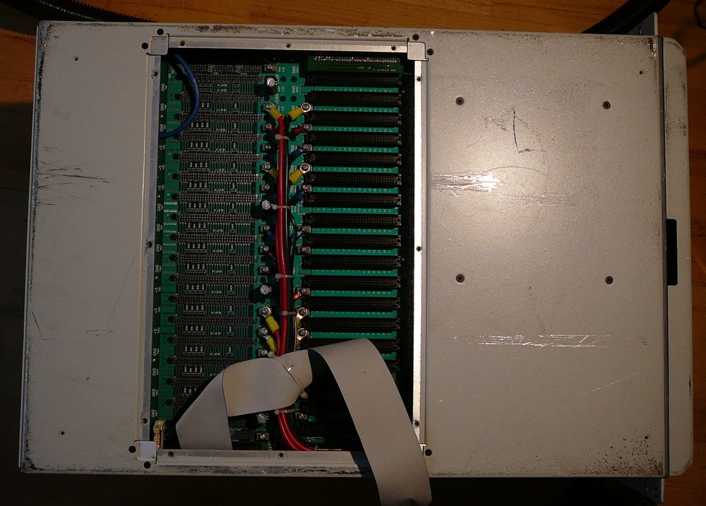
- VME64 Bus backplane with 20 slots
- Rugged design for e.g. military use
- LabView + MATLAB interfaces for data analysis
- VxWorks 5.1 as operating system
For the data processing cards in ICS-1000, software Library/Drivers exist for Solaris (1+2) and VxWorks. Complete source code of libs is available (see ICS-115 DAC Boad Datasheet page 11).I
As far as I understand, the case, power supply and VME64 backplane was taken as one part from the company “Carlo Gavazzi”. The CPU card is PowerPC-based from motorola, a 6 lines x 40 character display was taken from a company named “IEE”. Into this arrangement, ICS added it own set of data processing cards ICS 115 etc. Operating system is VxWorks 5.x.
The whole system seems to be out of the mid 90s.
Machine needs 430 Watts after being switched on :-)
Software
WindRiver VxWorks 5.3.1, Serial-No #1783328
Additional Infos
Herkunft (Vermutung)
Dieses Gerät hat einstmals zwischen 100.000 und 250.000 Dollar gekostet. Nur Forschungsinstitute, Universitäten, selbstforschende Konzerne und das Militär wird so ein Gerät kaufen und nutzen können.
An meinem Gerät sind Aufkleber entfernt, aber im Innern gibt es diese Aufkleber dann doch, und weisen auf die Bundeswehr als Vorbesitzer hin “(FWG/BW.”), konkret der “Forschungsanstalt der Bundeswehr für Wasserschall und Geophysik” in Kiel. Der ebay-Verkäufer war übrigens aus Bremen. Mein Gerät besitzt auch einen Ausgang, der mit “Hydrophone” bezeichnet ist, und Hydrophone werden für Sonarmessungen unter Wasser verwendet, was ein Hauptforschungsgebiet des FWGs in Kiel war und ist. Also würde ich sagen, das Teil kommt zu 99% Wahrscheinlichkeit vom FWG in Kiel. Link: http://de.wikipedia.org/wiki/Forschungsanstalt_der_Bundeswehr_f%C3%BCr_Wasserschall_und_Geophysik
Aus einer öffentlich zugänglichen eMail kann ich die Verwendung meines Geräts ableiten, es wurde als “Beamformer” verwendet. Beamforming ist laut Wikipedia ein Verfahren zur Positionsbestimmung in (Schall)wellenfeldern. Dies ist ein Verfahren, mit dem “passiv” Objekte geortet werden können, z.B. unter Wasser die Ortung fahrender ( schallaussendender) U-Boote.
Boards
In my device, 13 cards are used:
| Board name | Description | Number of cards |
|---|---|---|
| MVME2604 761 I/O | 1x CPU PowerPC. “Single Computer Board” with 32MB RAM, 333Mhz, SCSI, 100MBit LAN, Mouse & Keyboard connector, … | 1 |
| ICS 115-32 | Delta sigma DAC board, 32 bit - analog output, 50Khz Bandwidth | 2 |
| ICS 2200S | Front end DSP board, 640 MOPS | 8 |
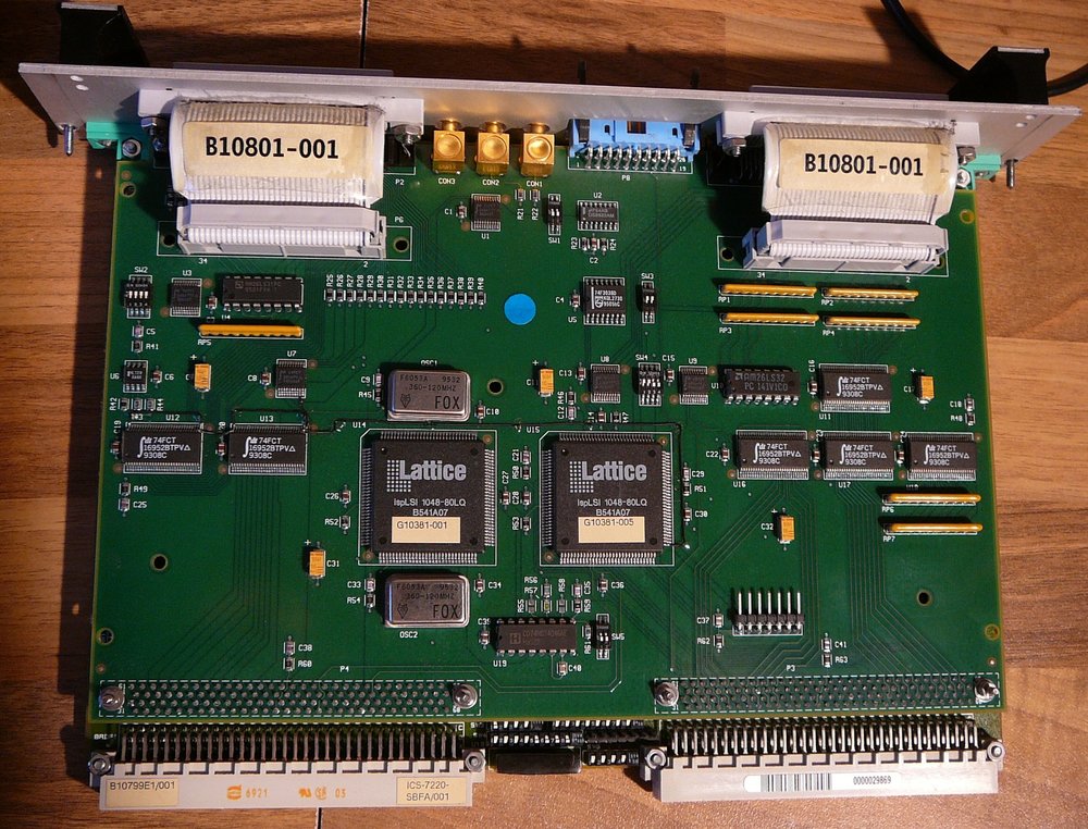
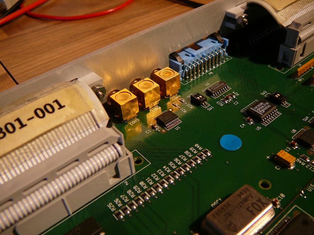
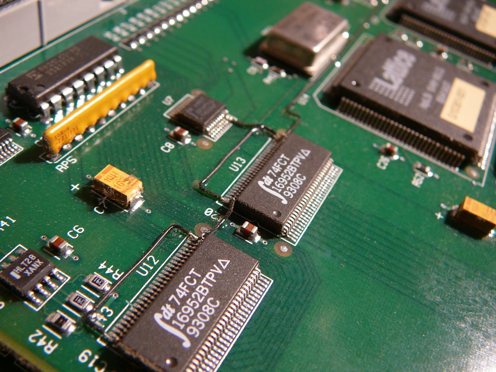
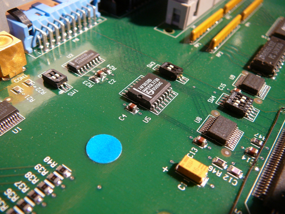
| ICS 7220-SBFA | Store of data / Interface to data recorders | 1 |
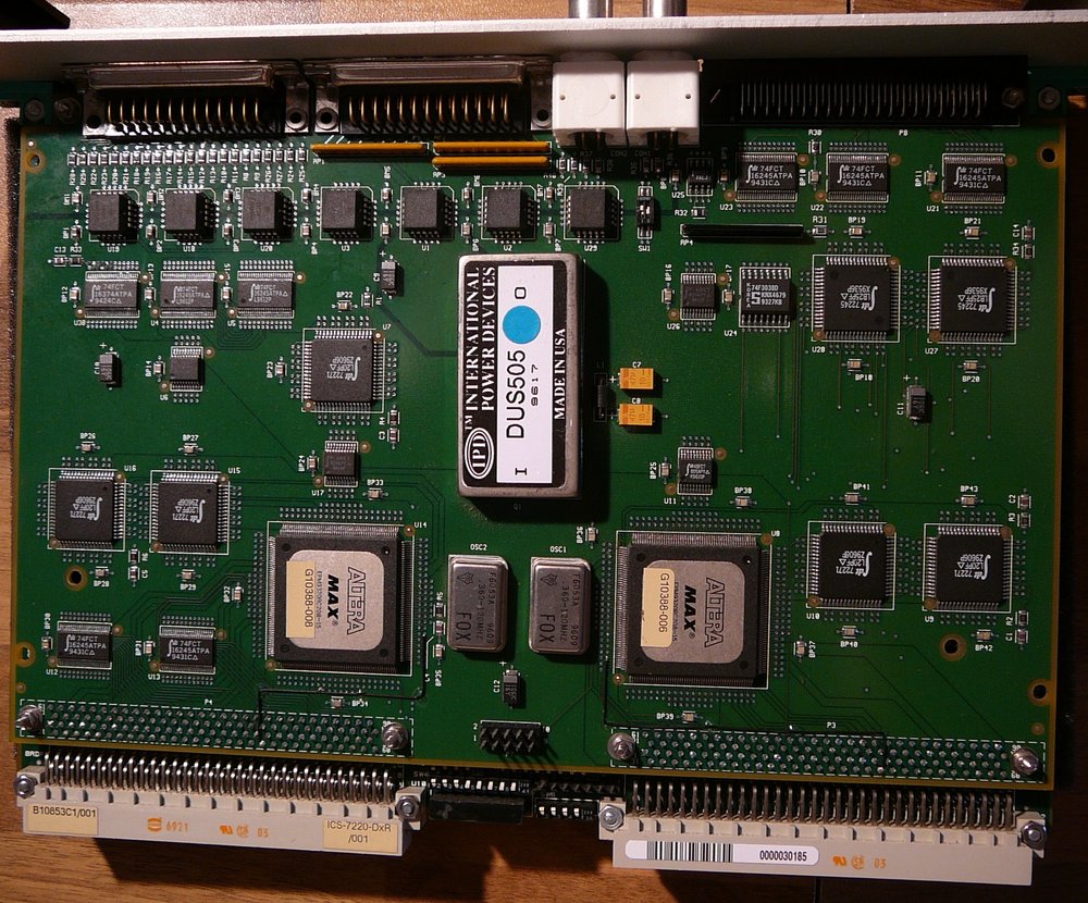
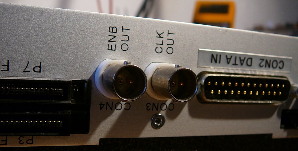
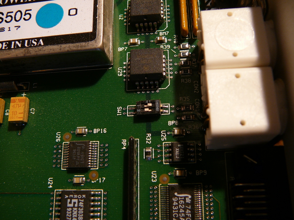
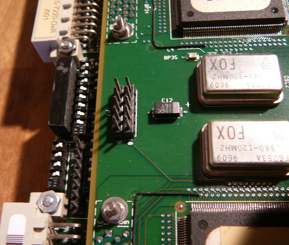
| ICS 7220-DxR | Interface to Sony DIR100 Recorder (High Speed Data Recorder) | 1 |
| ICS 7220-ALU | Data routing and formatting board | 1 |
Storage media
- SCSI harddisk NEC DSE 2100S 2GByte, SCSI2.
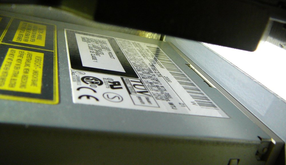
- Matshushita Laser Disk Drive LKM F-934-1. Can read 1,44, 2,88 and 120MB floppys. The 120MB floppys are optical. Media name is “LS120”.
MVME2604 CPU
ABMVME2604-1331M REV B –> “333 Mhz PowerPC-CPU MPC604, 16-256MB ECC DRAM, 9MB Flash” (see Installation Guide Page xvii)
My Models Ethernet MAC: 08003e2af939 Contains Firmware: PowerPC Bug (PPCBUG) in ROM
Usually, the CPU board is connected via a “transition module” to peripherals ( like SCSI disks, serial/parallel interfaces, LAN). Motorola offers two different transition boards:
- MVME712M
- MVME761
They differ in the number and types of interfaces they offer.
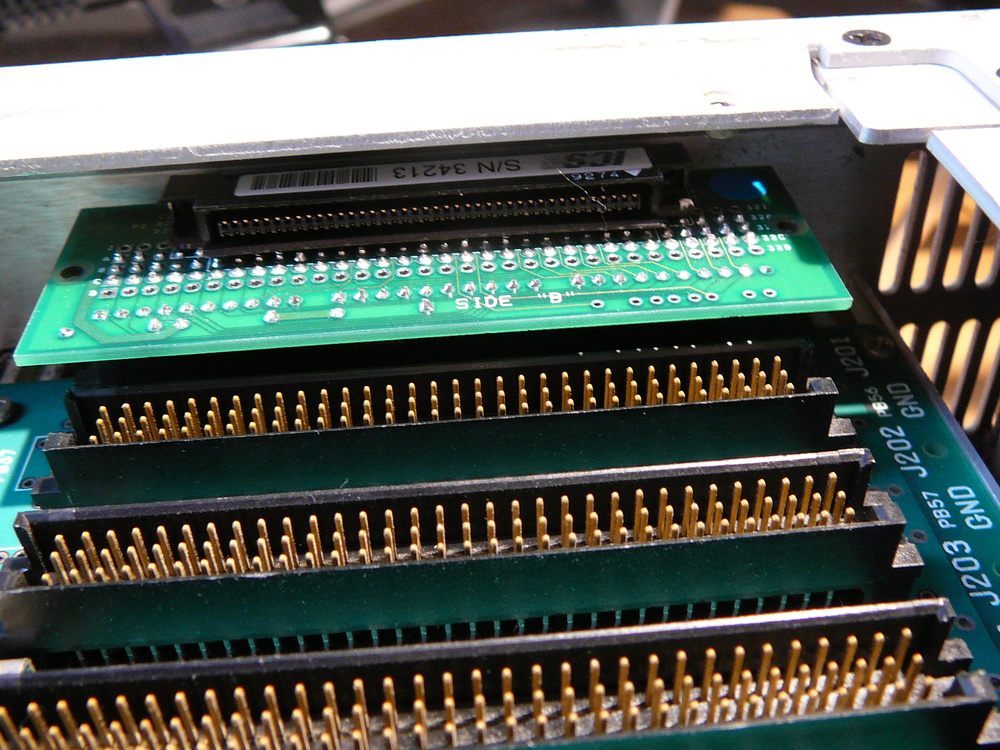
ICS-1000 does not use such a prebuild transition module. The board’s connector with bus signals go to a small adapter card named “P2”. This PCB is build by ICS (Note: Motorola also offers a P2 board between CPU and transition module). The P2 module may only add SCSI termination and offers another 80-pin(?) connector that is routed via cable to another small PCB made by ICS. This second board offers 2x serial, 1x SCSI and 1x LAN connectors. The SCSI connector is routed to Harddisk and Floppy drive. One serial connector is routed to SubD9 connector at the back of the device, the other one goes to the PEP VFD display via a null modem adapter. So the second board seems the ICS replacement for the Motorola transition board.
NVRAM backup battery
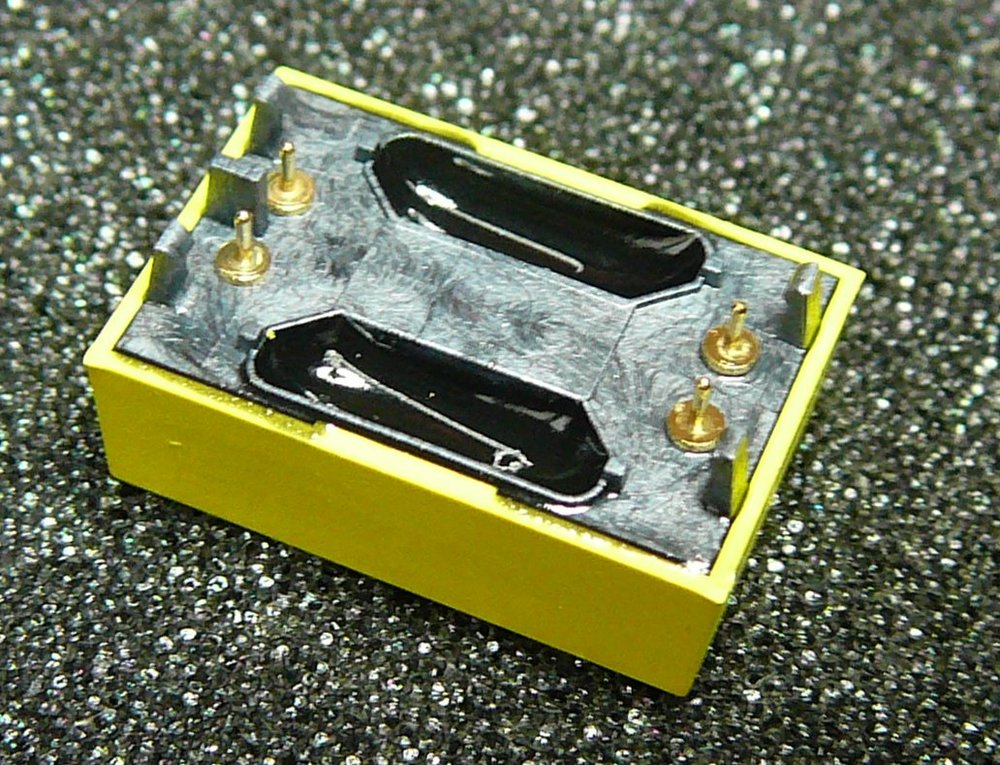
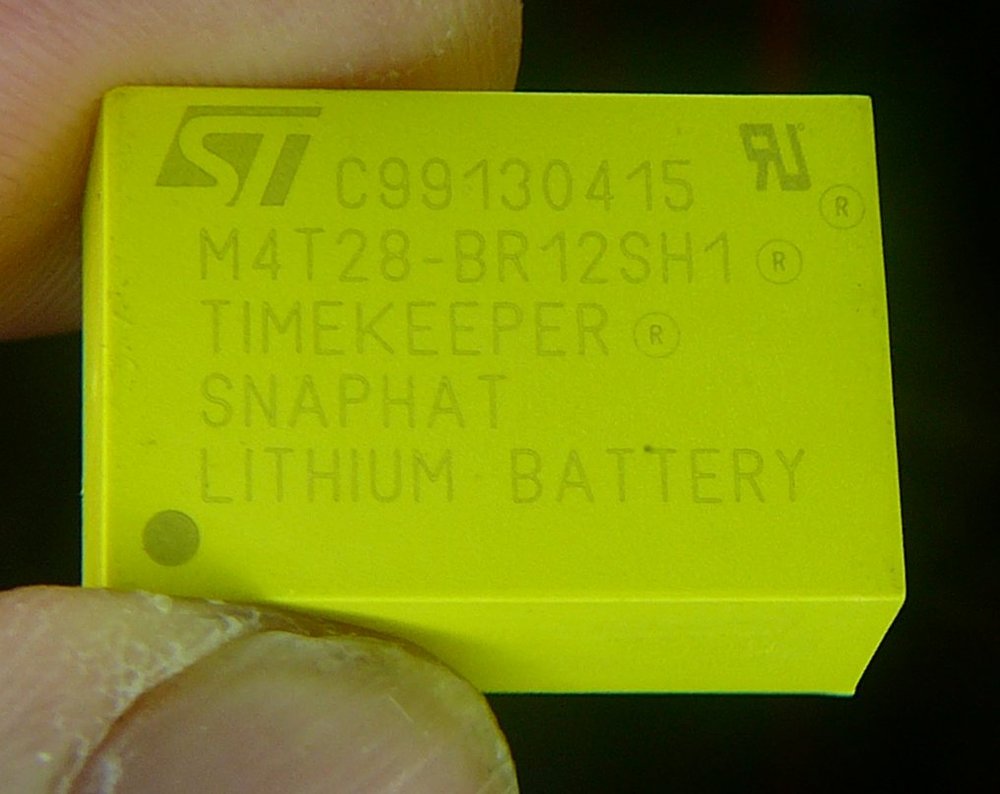
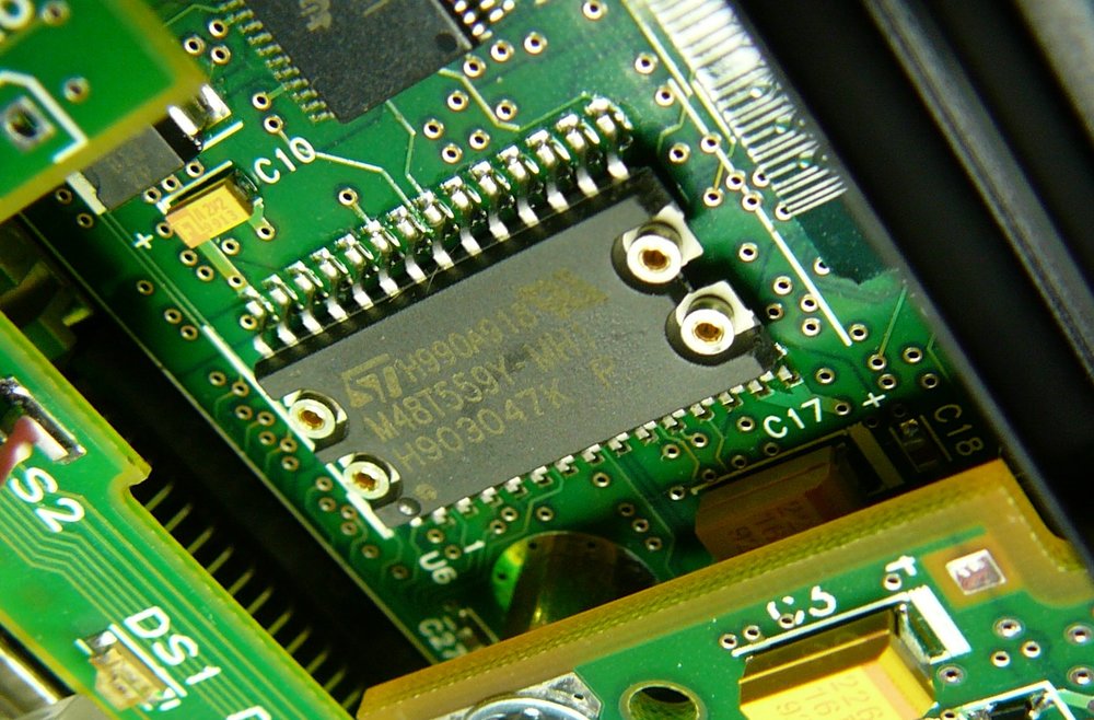
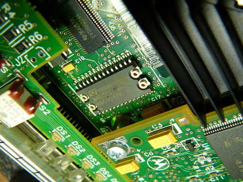
The NVRAM backup battery was dead on my CPU board. Type: 4T28-BR12SH1 - TIMEKEEPER SNAPHAT, XTal 32Khz + Battery 2,8V, 48mAh.
I found such a battery for ~4 euro in ebay and replaced the dead one.
Power supply, case VMEBus backplane
Inside the case there is a plate “MUPAC a Carlo Gavazzi Group Corporation. Model 5107WLF20TK-100 .”
I assume the number refers to the complete housing including backplane, case, power supply.
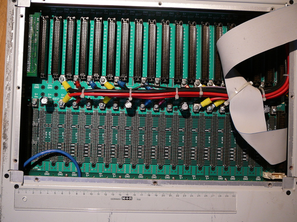
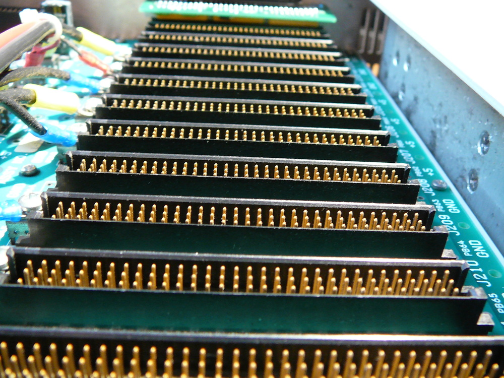
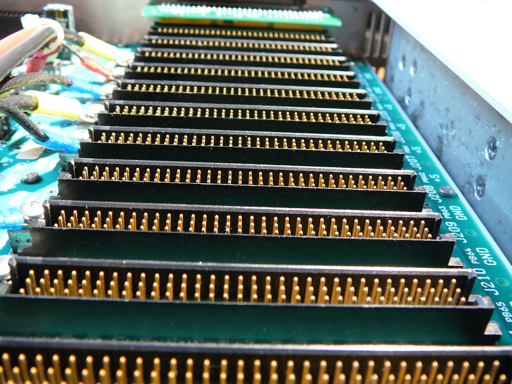
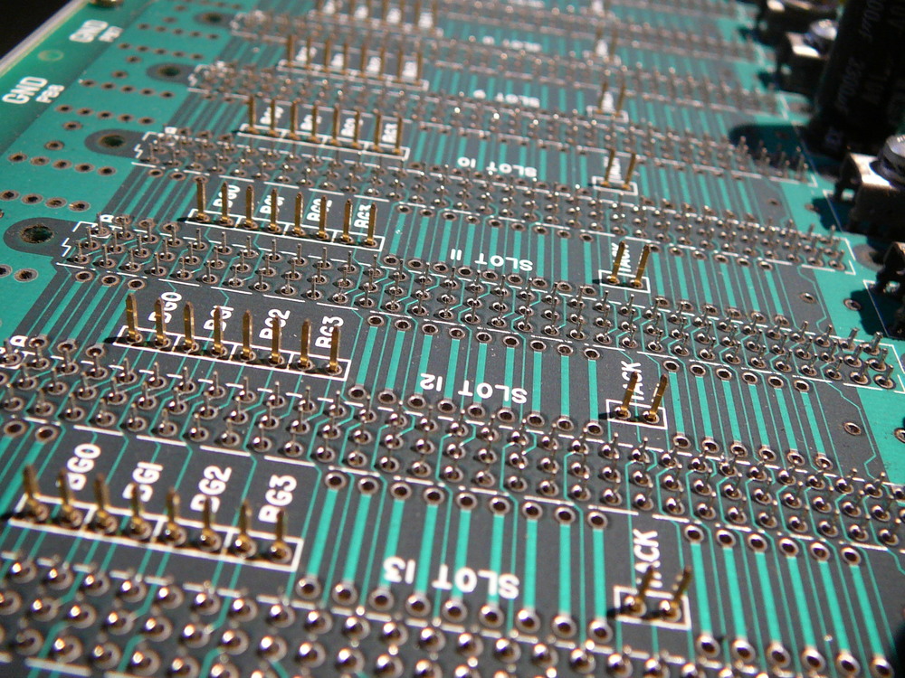
Carlo Gavazzi is a company that builds VME solutions, cases etc. Todays model numbers 5127… are cases from Carlo Gavazzi MUPAC with 20 lots. Carlo Gavazzi also produces backplane PCBs.
The power supply is a 1000 Watts one (no joke) with 5/12 volts.
Information on ICS-1000 and its components
(text below taken from http://defense.ge-ip.com/products/ics-115a/p2039 and from old ICS website http://www.ics-ltd.com/ via Internet Wayback machine.
SYSTEM-1000: Fully Integrated Data Acquisition Solution
SYSTEM-1000ES is an extension product that includes embedded storage. It
includes 12 VME 64x slots and 144 Gbytes of RAID storage. The RAID storage
supports sustained data transfer rates of over 90 MBytes/s.)

The SYSTEM-1000/1000ES system is typically controlled from a PC via Ethernet.
Extensive LabVIEW software is included for the PC for analysis and display.
Options are also offered for high-speed data delivery to PC via FPDP.

The SYSTEM-1000 is particularly well suited for implementing any one or a
combination of the following:

- Simultaneous acquisition of a large number of analog channels;
- Real-Time data recording/playback;
- FibreChannel transmission of high-speed sensor data;
- Simultaneous analog output of a large number of channels;
- Front-end signal processing, such as FIR filtering, demodulation, beamforming,
  FFT, etc. and;
- General sonar/radar receive, transmit and Sim/Stim processing.

Each system is packaged in a standard 19" rack-mountable fan-cooled enclosure,
which houses up to twenty (20) VMEbus boards (12 for SYSTEM-1000ES) along with
an integrated dual-voltage 1000 W power supply. A powerful embedded processor
running the VxWorks real-time operating system handles the control of each
system. All of the software required to configure and control the SYSTEM-1000 is
stored on an internal hard drive and is automatically loaded in to the memory of
the embedded processor upon power up.

-     An elegant 19" rack-mountable enclosure (12" high);
-     Up to 20 slot VMEbus backplane;
-     144 GB RAID storage (SYSTEM-1000ES);
-     Over 90 Mbytes/s sustained data recording speed;
-     A 1000 Watt power supply;
-     Front Panel Touch-Screen Display;
-     Floppy and hard drives;
-     All system software;
-     Host-independent graphical user interface (GUI) for control; and
-     Easily upgradeable to adopt to future needs.

The SYSTEM-1000 is particulary well suited for implementing any one or a
combination of the following:

-     Simultaneous acquistion of a large number of analog channels;
-     Real-Time data recording/playback;
-     FibreChannel transmission of high-speed sensor data;
-     Simultaneous analog output of a large number of channels;
-     Front-end signal processing, such as FIR filtering, demodulation, beamforming, FFT, etc; and
-     General sonar/radar receive, transmit and Sim/Stim processing.
ICS-115A 32-Channel 100Khz/Channel Delt-Sigma DAC boad
The ICS-115A is a 32-channel VMEbus DAC board that offers true 16-bit precision
and update rates of up to 100 kHz/channel. The use of delta-sigma DACs offers a
high degree of precision and digital interpolation, which moves the aliased
image away from the signal band. This signigicantly relaxes post-filtering
requirements. The ICS-115A provides differential outputs with high current
drivers to directly drive large capacitive loads, and a 2-pole reconstruction
filter for each DAC output is provided for each channel.

The ICS-115A board is ideal for sonar transmit, real-time simulation and digital
audio applicatons. The ICS-115 is a slower speed version of the ICS-115A board
that can operate at up to 50 kHz/channel update rate.

This product was discontinued on 01/18/2010.

MODEL DESCRIPTION ICS-115-yy VMEbus DAC board. Standard 50 kHz version is
supplied with 35 kHz reconstruction filter. Consult the factory for other filter
options. yy: number of channels (8, 16 or 32) ICS-115A-yy VMEbus DAC board. 100
kHz version supplied with 65 kHz filter. yy: number of channels (8, 16 or 32)
DRV-115-VXW Software device driver for VxWorks operating system. DRV-115-SSS
Software device driver for Solaris operating system.
ICS-2200 Multi-Channel Time-Domain DSP Board
The ICS-2200 board is a Sharp LHBDSP9124 based DSP board that has been designed
to solve compute-intensive front-end DSP problems with a sustained computing
power of up to 640 MOPs in one VMEbus slot.

Some features of this board are:

- Multi-channel FIR filtering/decimation;
- Complex demodulation;
- Replica correlation;
- Real/complex beamforming;
- Inverse beamforming, etc.

The ICS-2200 board is available in single (ICS-2200B, which replaces ICS-2200S)
and dual (ICS-2200D) versions. The latter includes a second DSP device on a
daughter card. The SHARP DSP chip offers 24-bit data, 24-bit coefficients and
60-bit accumulation. The board includes four specially designed hardware
sequencers that control the operation of the board and manage the data flow. The
I/O memories are dual-banked to allow apeturing or arbitrary selection of
channel data for processing. The coefficient memories are also dual-banked to
allow parameter updates without interrupting processing.

No. of Input Channels (NI):    Lesser of 8192 and (16384/ND) No. of Outputs (
NO):    Lesser of 8192 and (32768/NI-1) Number of Coefficients (NT):    4 to
8192 (even numbers only) Decimation (ND):        1 to 255 Delay for Beamforming
and Inverse Beamforming (NDEL):   Lesser of 4096 and (1048576/NI) Interpolation
Resolution (Upsampling Ratio):    Over 1000 : 1 (Typical) Coefficient Memory
Size:        2 x 16 K x 24 (Dual port) I/O Memory Size:        4 x 16 K x 32
History Data Memory Size:       2 x 512 K x 24 VMEbus Interface:
A32/24/16, D32 vectored interrupts VSBbus Interface:       A32/D32 Polled
interrupts FPDP Interface:         2 reconfigureable FPDPs (80 MBytes/s) Power:
3 A @ 5 V for ICS-2200B 6 A @ 5 V for ICS-2200D Throughput Rate (Fs):   80 MHz
/ (NO x NT x NIA + NI +

96) [For beamforming, NIA is not equal to NI when the number of inputs being processed is different from the total number of inputs, i.e., multiple aperture beamforming.]
    80 MHz / (NO x NT x NI x 96) [For filtering] {Specifications are subject to
    change without notice}

MODEL DESCRIPTION ICS-2200B VMEbus DSP board with a single SHARP device
ICS-2200D VMEbus DSP board with two SHARP devices DRV-2200-VXW Software device
driver for VxWorks operating system ASW-2200 Application software for the
ICS-2200
ICS 7220 SBFA and DxR
FPDP Interface and Special Function Board The ICS-7220 is a 6U VMEbus board that
is designed to simplify interfacing to external equipment. In order to reduce
the time and cost of developing special interfaces, the ICS-7220 board includes
provisions for incorporating a daughter card.

Custom daughter boards for the ICS-7220 can also be developed by the user. ICS
provides full technical assistance, free of charge, to any user wishing to
develop a daughter card for the ICS-7220 board.

Standard daughter cards are now available for interfacing a wide variety of data
recorders for data formatting of FPDP stream, and for generating random noise.

The ICS7220 DxR is an interface to a sony high speed data recorder.
ICS-7220 ALUB: FPDP Data Routing and Formatting Board
The ICS-7220 ALUB daughter card includes two input FPDP ports and one output
FPDP port. Each input path includes a dual-port memory and a barrel shifter. A
sequencer memory can select which data words (channels) to output from each
dual-port in an arbitrary fashion. The ALUB unit can add, subtract and
selectively merge the two FPDP data streams with the Datum real-time clock data.
The 64-bit Datum clock input is sampled at the input FPDP frame rate and it is
divided into two 32-bit words for merging with the input data. Note that while
the data source for the primary input path is FPDP, the data source for the
secondary input path can be either FPDP (daughter board) or VME64/VSB (mother
board). The output from the ALUB is available via the FPDP at the input frame
rate (either Main or Aux. FPDP). If the Aux. FPDP input is at a decimated frame
rate, the output frame rate must be at the Main FPDP input frame rate. The
ICS-7220-ALUB board can select any data word (channel data) from the primary,
secondary and output data path for storage into the mother board's swing buffer
memories for VMEbus/VSB access. The ICS-7220 board also includes a 16-bit D/A
converter for analog conversion of any selected output channel.

-     Arbitrarily select data words from either inputs for FPDP output;
-     Merge two input FPDP data streams;
-     Merge Datum real-time clock data with the FPDP inputs;
-     Merge or add VME64/VSB data with the main FPDP input;
-     Select any channel (or data word) from each input for VME64 access;
-     Select any FPDP output data word for D/A output; and
-     Software device drivers for VxWorks.

MODEL DESCRIPTION ICS-7220-ALUB General purpose interface motherboard.
DRV-7220-ALUB-VXW Software device driver for VxWorks operating system.
Front Display
A “Vacuum Fluoreszent Display”, green, 6x40 chars. Model: PEP 04226-01 Out of the series “PEP Touch Screen Interface Display” from IEE. (http://www.ieeinc.com/vacuum-fluorescent-displays)
The UL-recognized IEE Peripheral Entry Panel (PEP) is an interactive terminal
assembly integrating a 6-line by 40-character VFD with an infrared switch
matrix. Interaction with the host system occurs when the operator reads
displayed messages and responds by finger contact with a touch sensitive switch
location on the screen. Since the switch matrix uses optical technology, no
annoying grids are present to degrade the appearance of the display.

-     Bright, Easy to Read 6-line by 40-character VFD
-     Infrared Touch Screen Immune to Ambient Light
-     Single Piece, Drip-proof, Polycarbonate Bezel
-     32 Kilobytes of Battery-backed RAM for Message Storage
-     EIA-232 and EIA-422 Serial Interfaces at 1200 or 9600 Baud
-     Single +5 VDC Power Supply
-     Extended -40°C to +85°C Operating Temperature Range Available"
Images
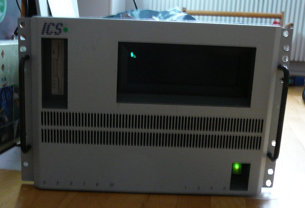 Front of the device, switched on
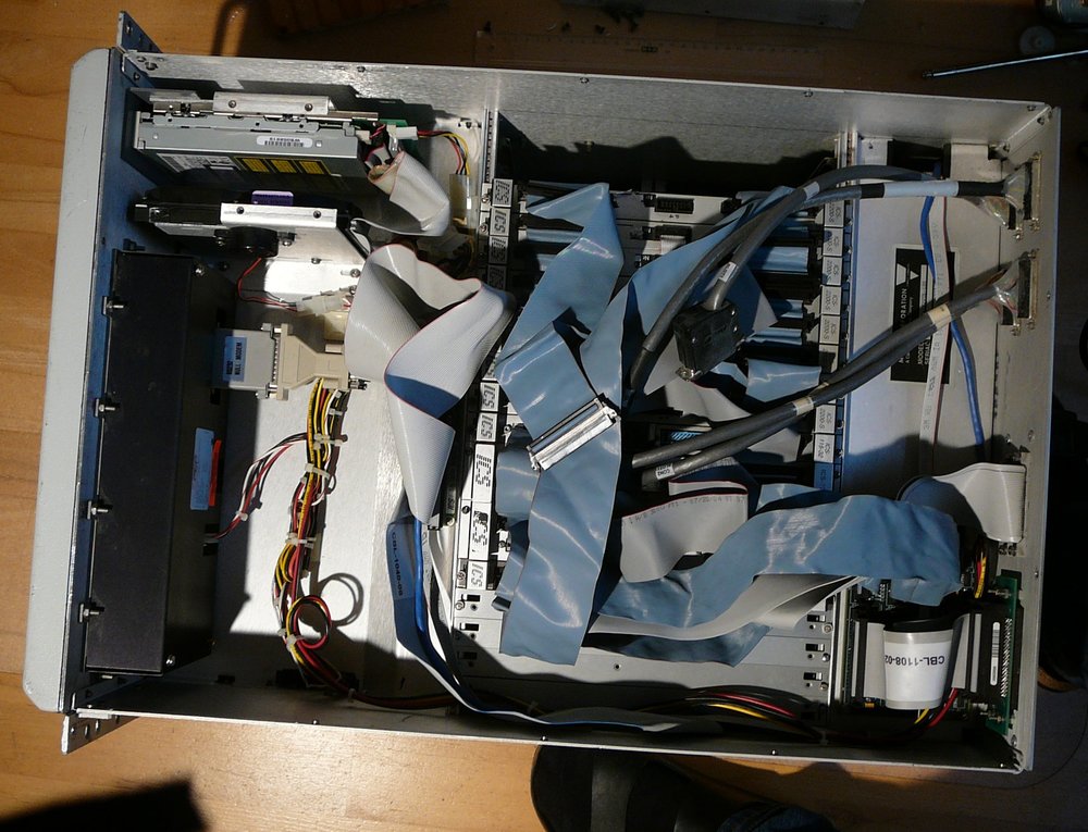
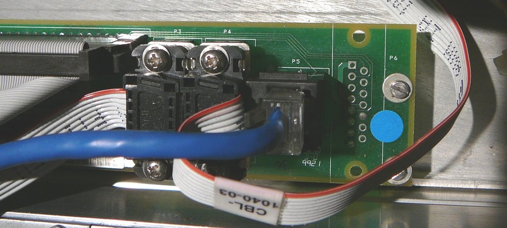 “Breakout board”, 2 x serial connectors
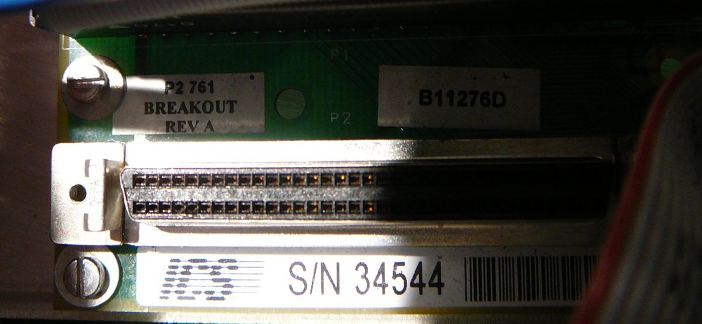 “Breakout board”, SCSI connector
 Harddisk and floppy drive
Display
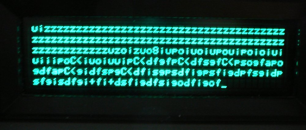 Display attached to a PC and some data was enetered
via PCs keyboard - the display works…
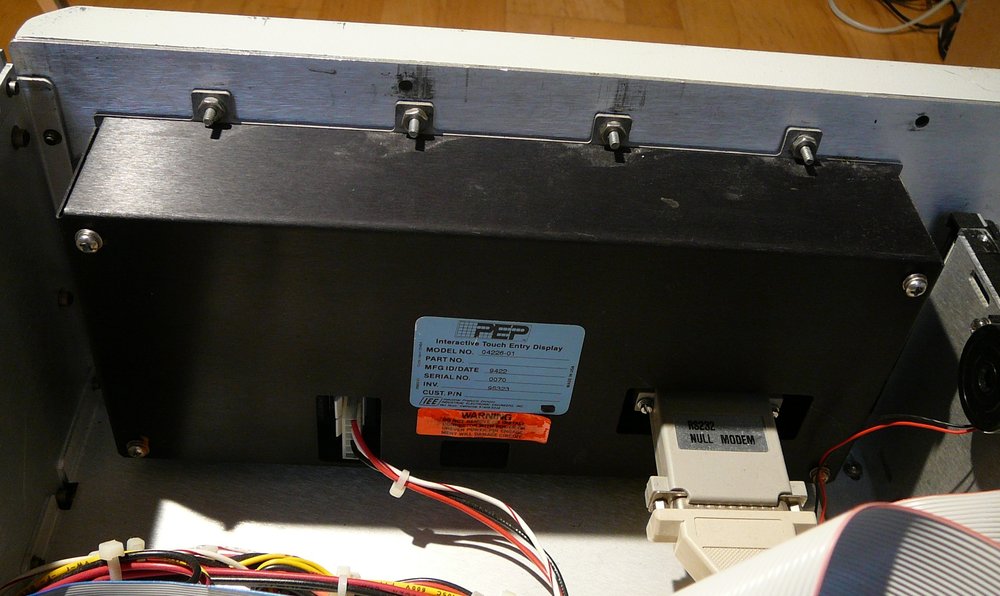 Back of display
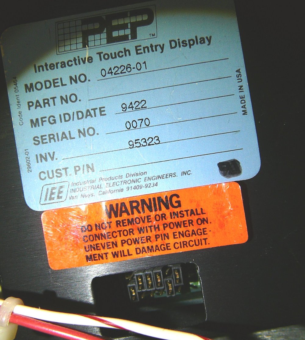 Display: Note jumpers at bottom of image
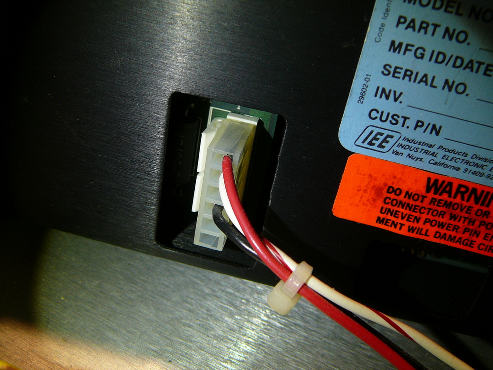 Display: power supply connector
Laser Disk Drive
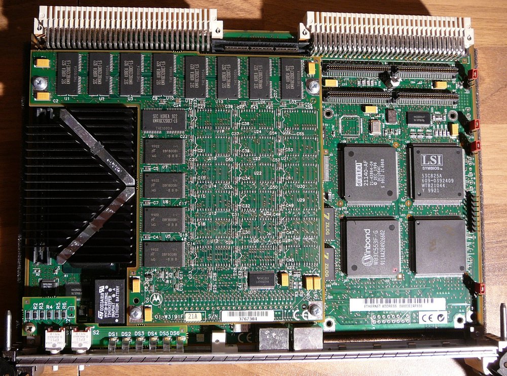
MVME2604 761 I/O CPU Board
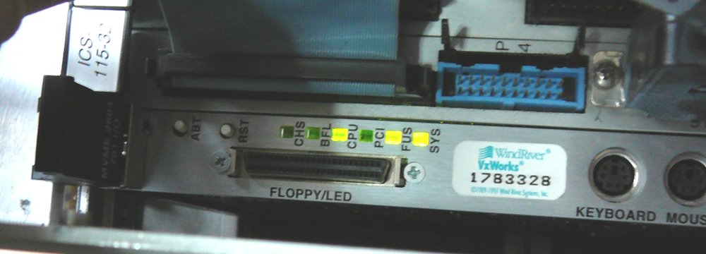 Board LEDs after switched on
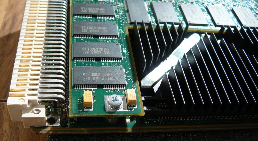
 On top of the main board, there is a daughter "
mezzanine" board carrying additional RAM and ROMs. My daughter board adds
another 16MB to the 16MB that are already on the main board. Furthermore, it adds
8MB ROM.
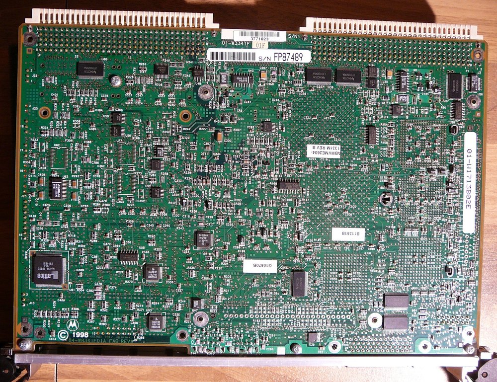 Bottom side.
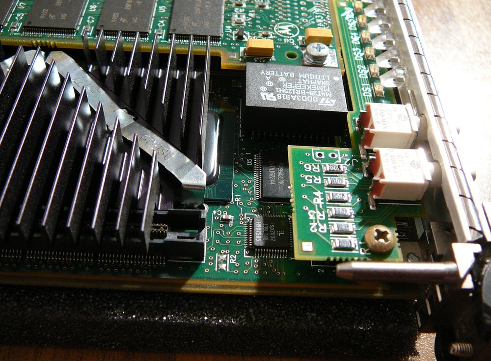 Here, the NVRAM backup battery can be seen
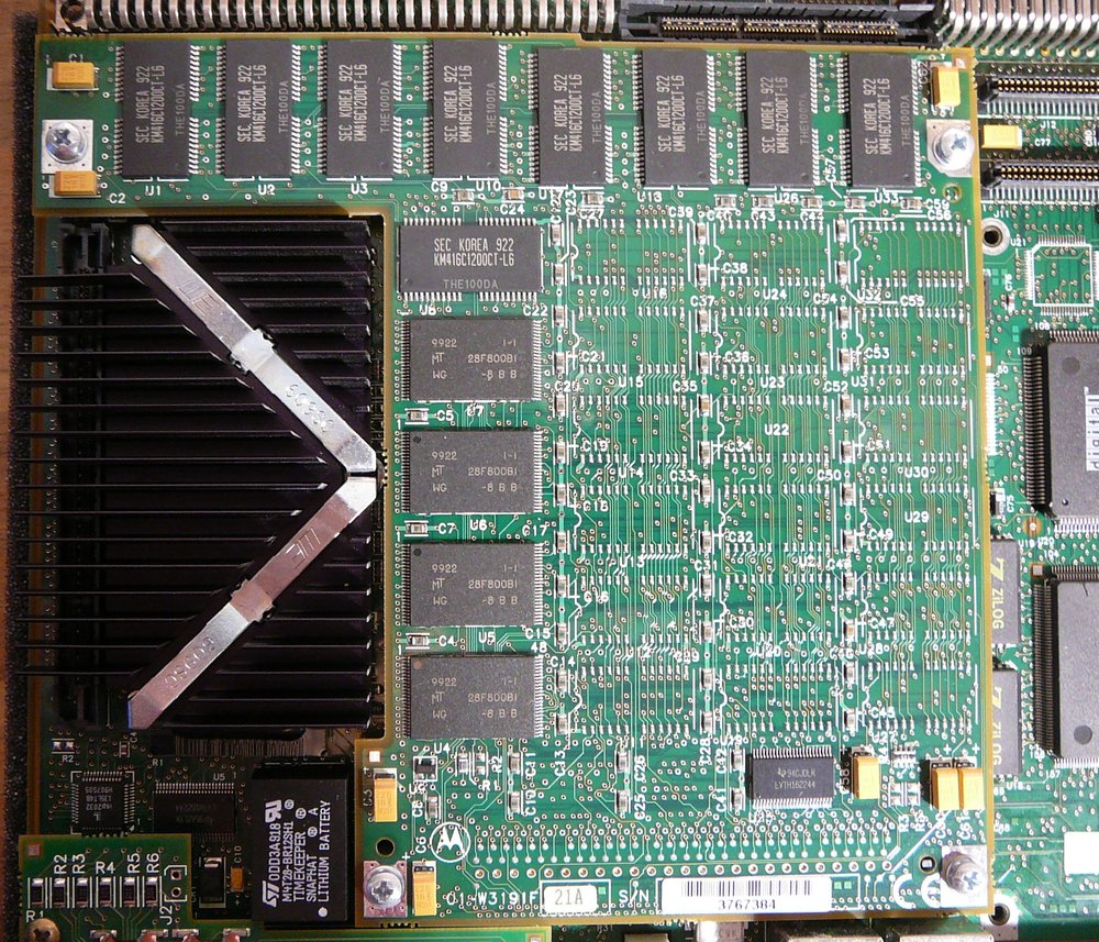 The RAM/ROM mezzanine card
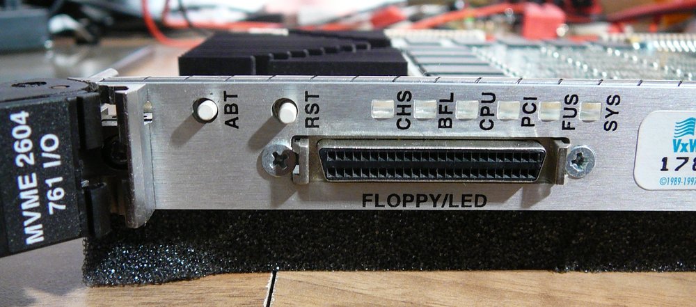
ABT=ABORT, RST=RESET CHS= BFL= CPU= CPU Clock PCI=PCI Bus Activity FUS=FUSE ok/defect SYS = Board is running as VME Bus Controller yes/no
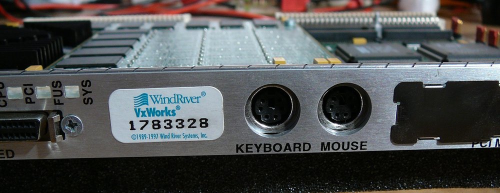
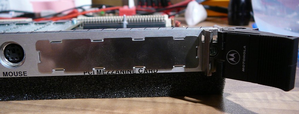 No PCI Mezzanine card installed here

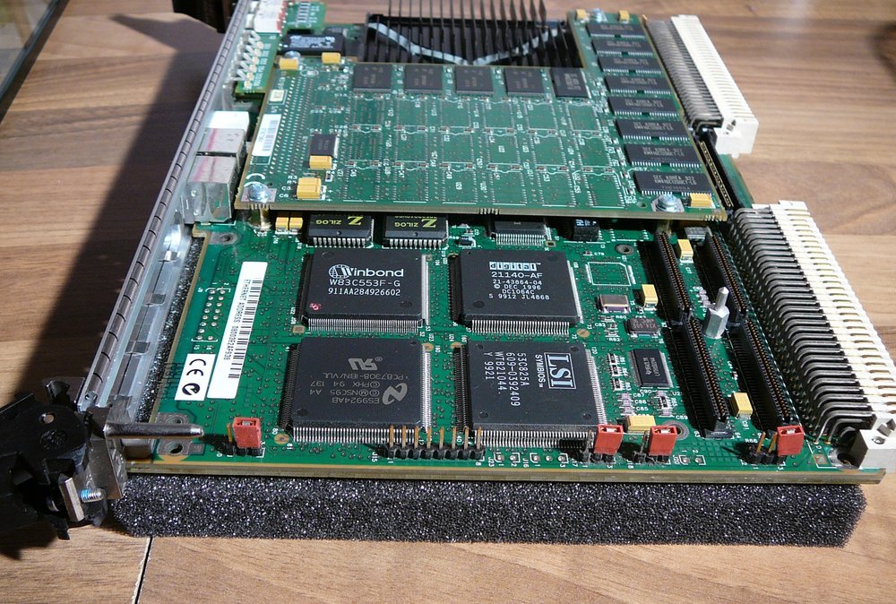
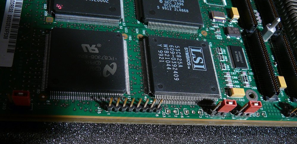
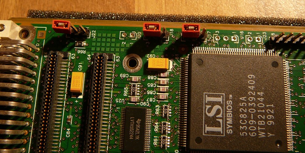
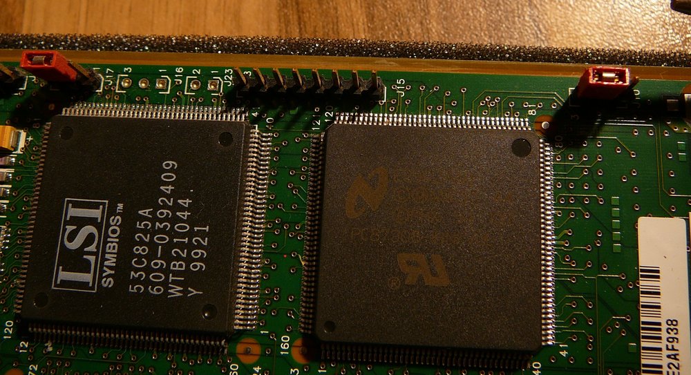
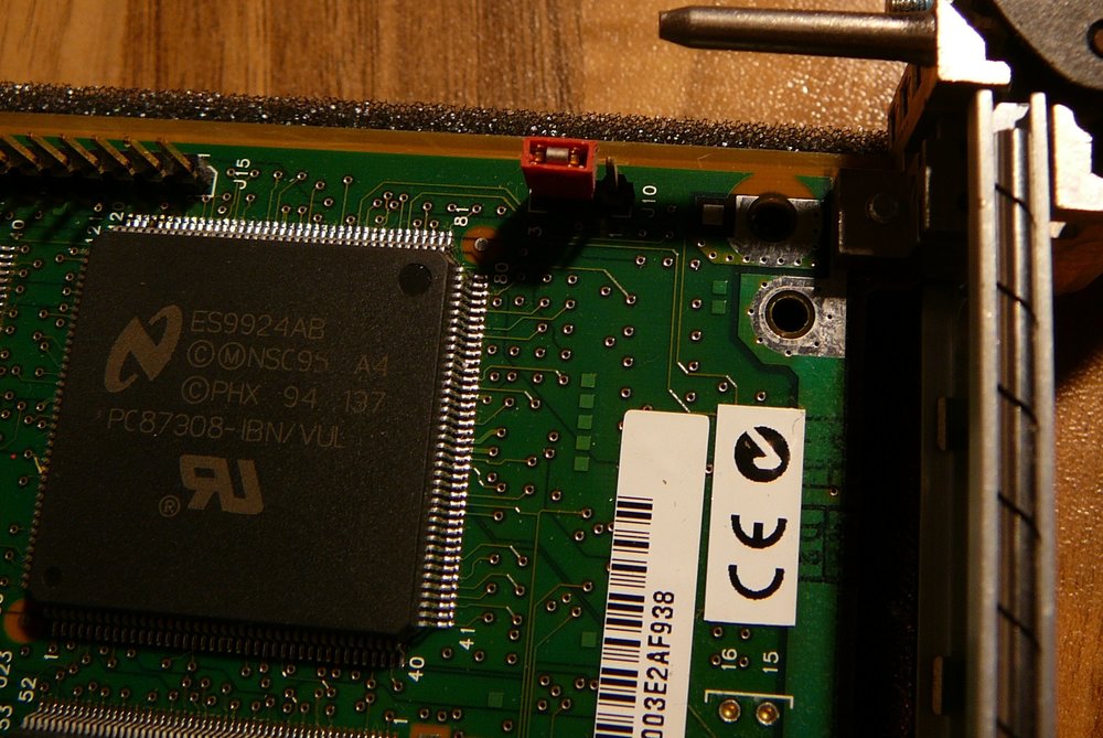
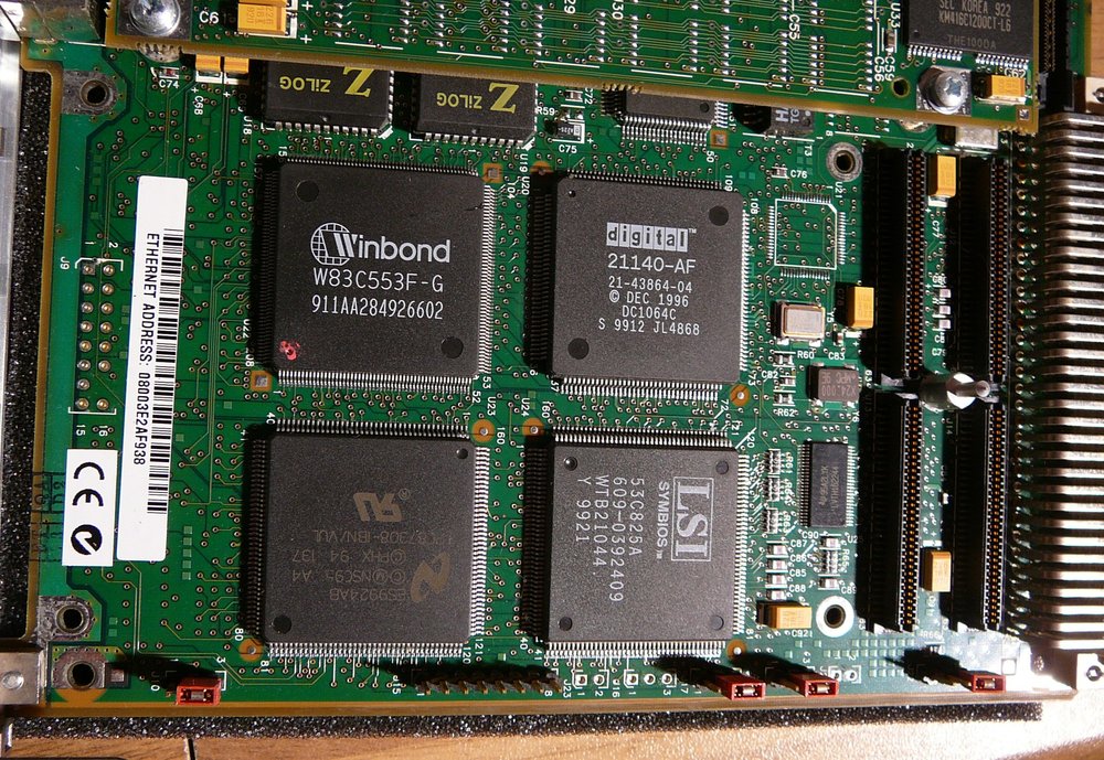
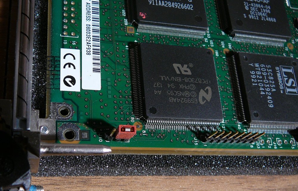 These our big chips are the interface devices for
SCI, Network, serial, VMEBus etc.
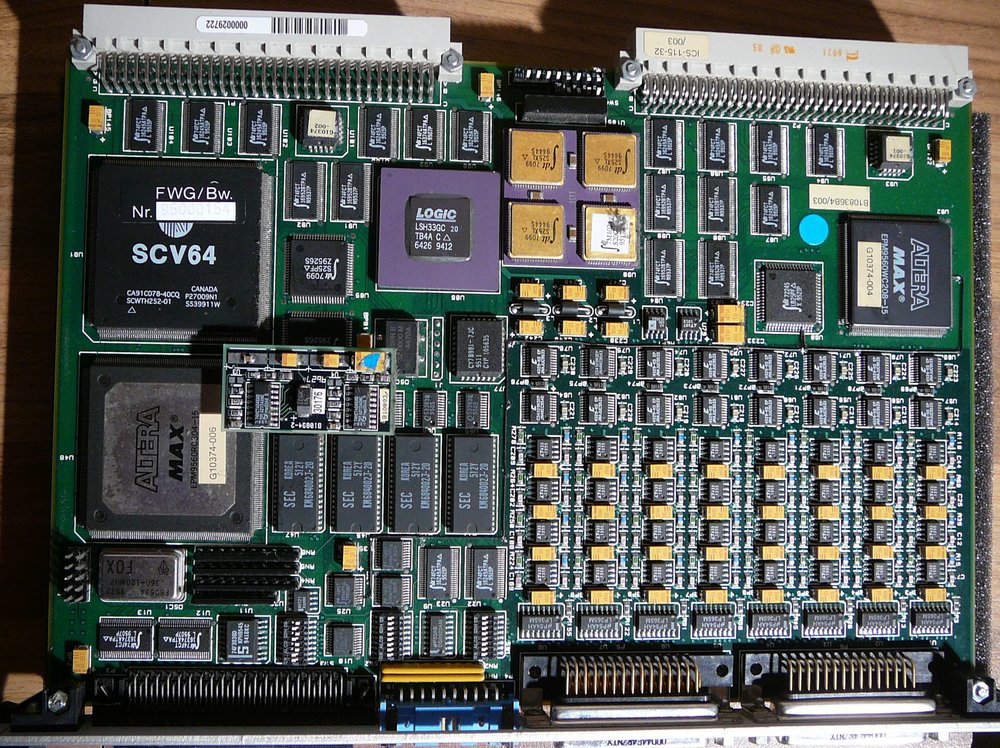
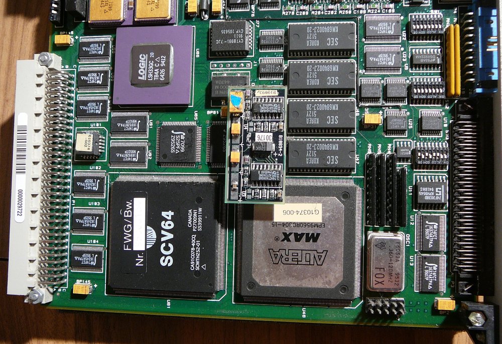
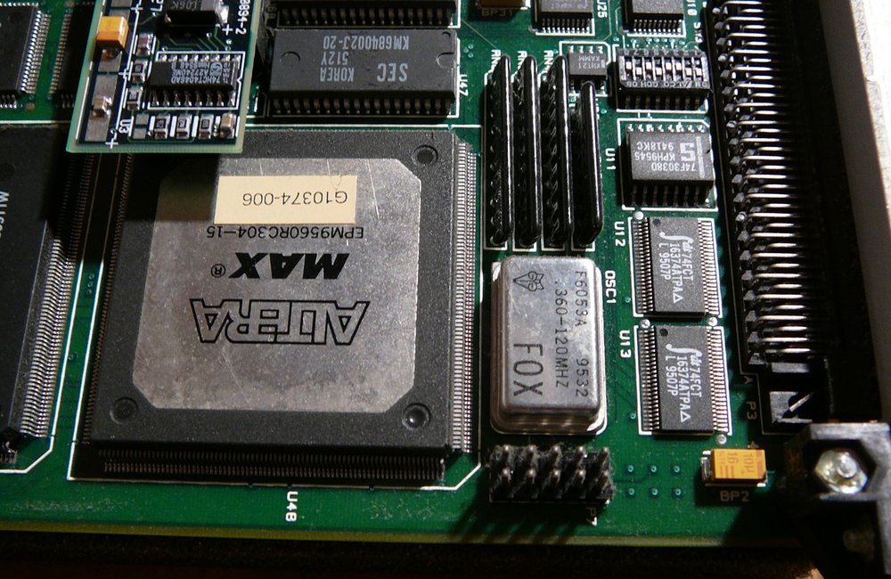
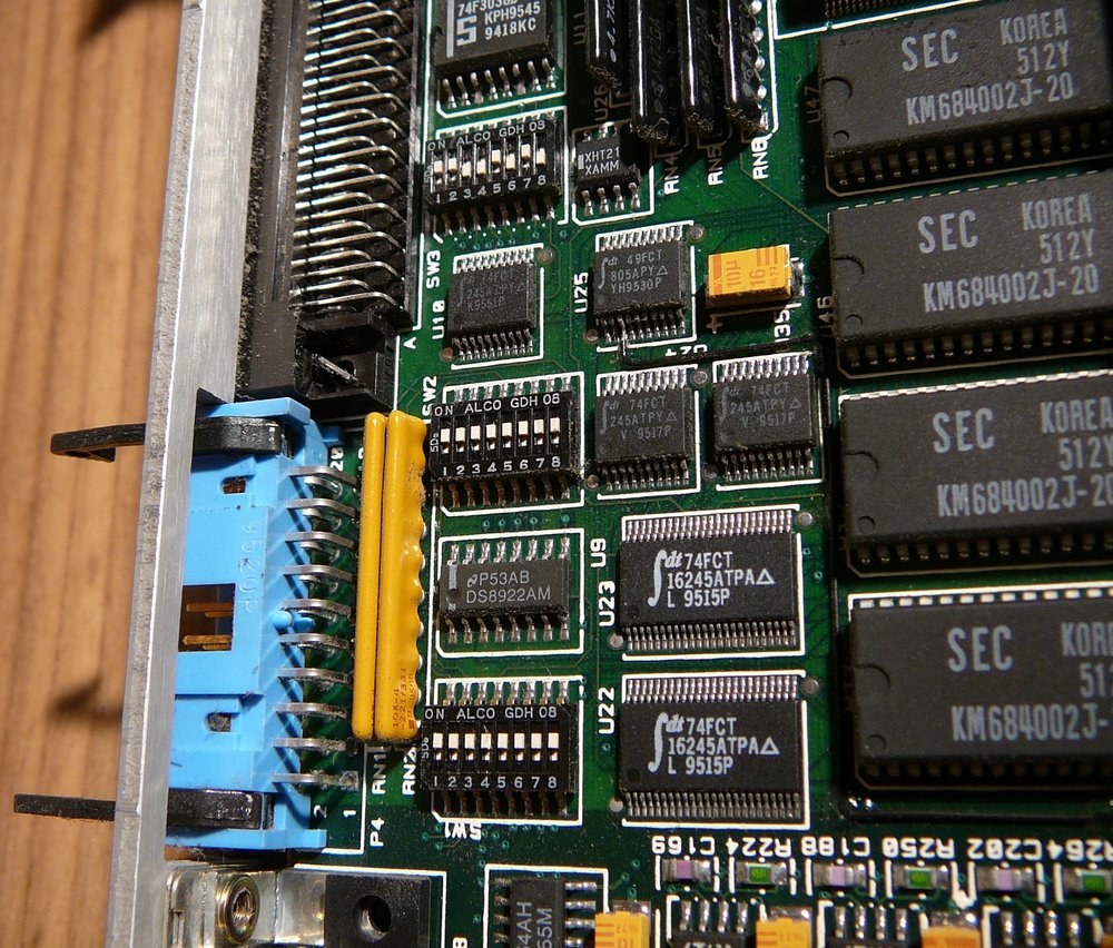
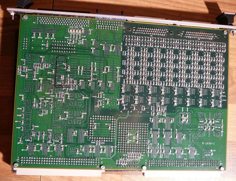
ICS 115-32 DAC Output Board

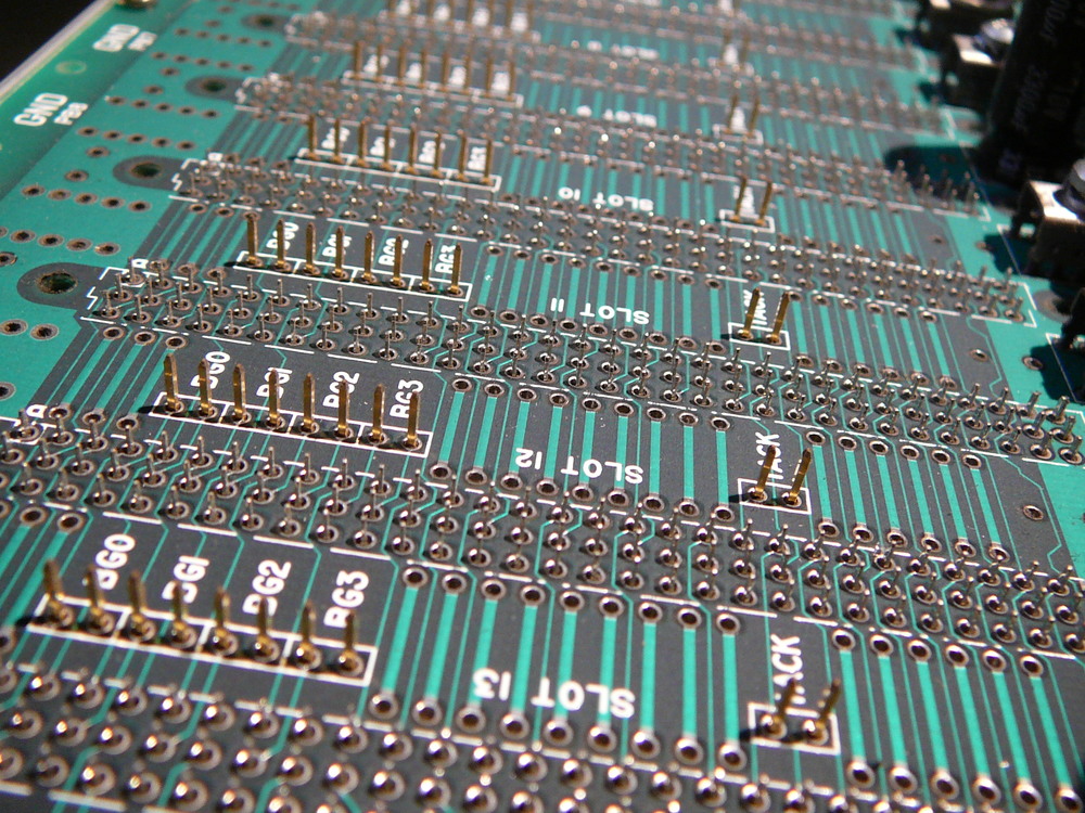
VME64 Backplane

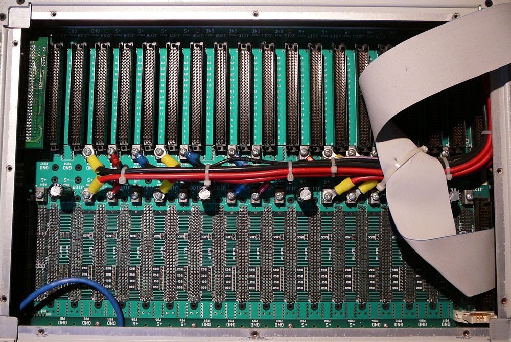
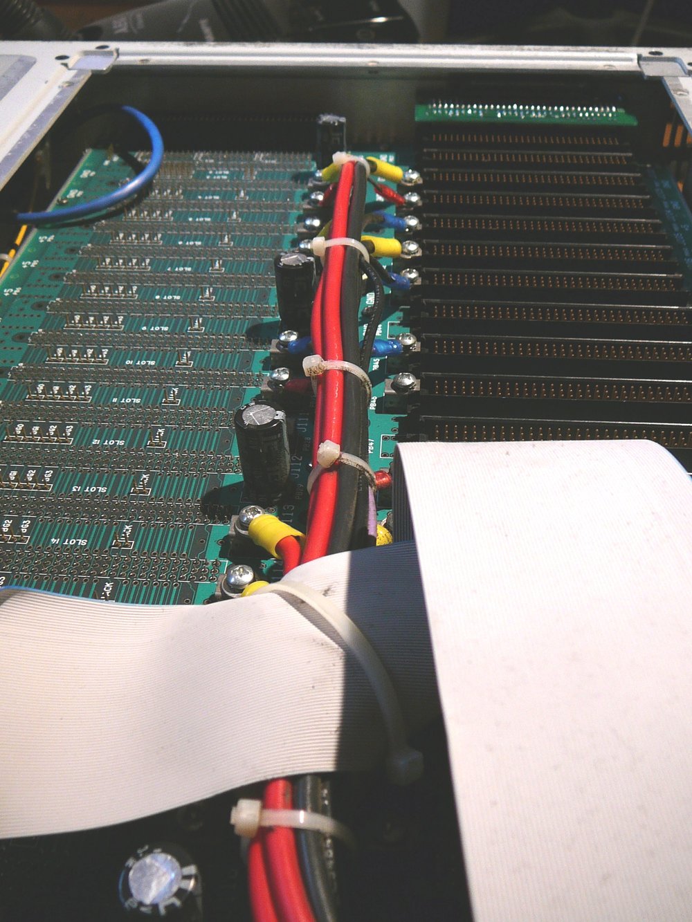
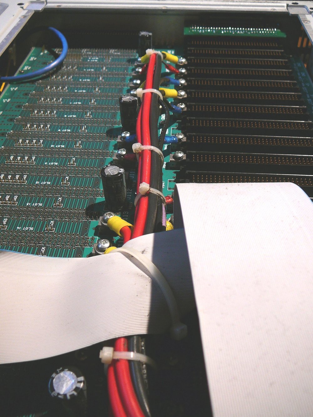
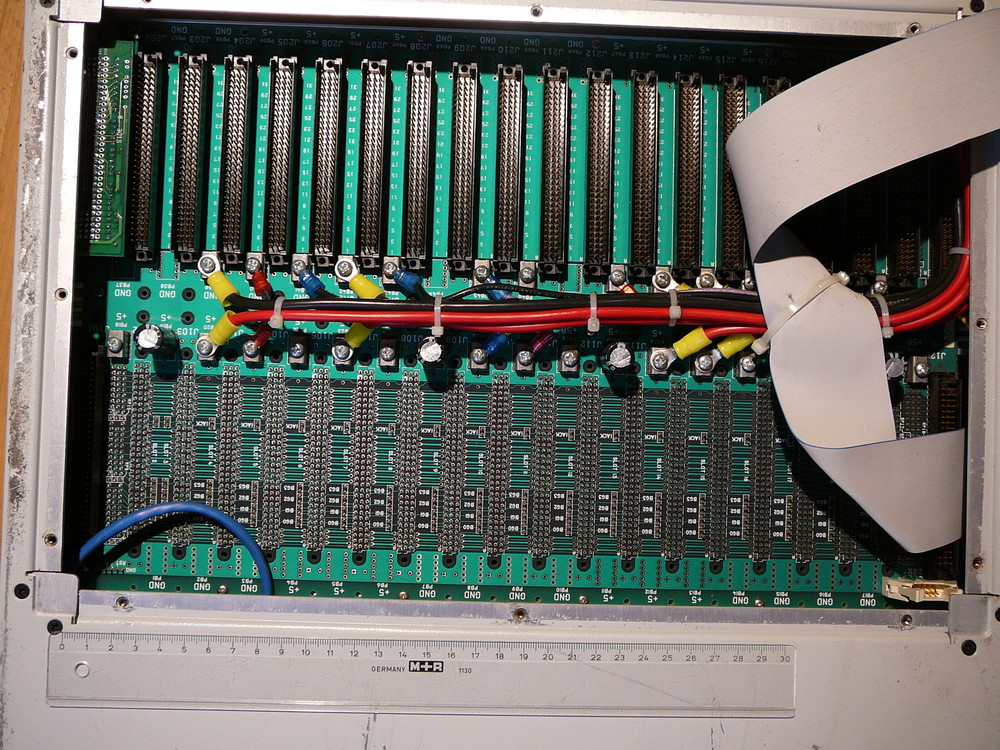
 P2 Adapter
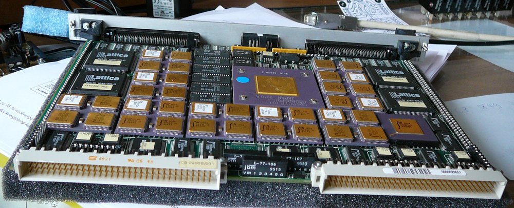
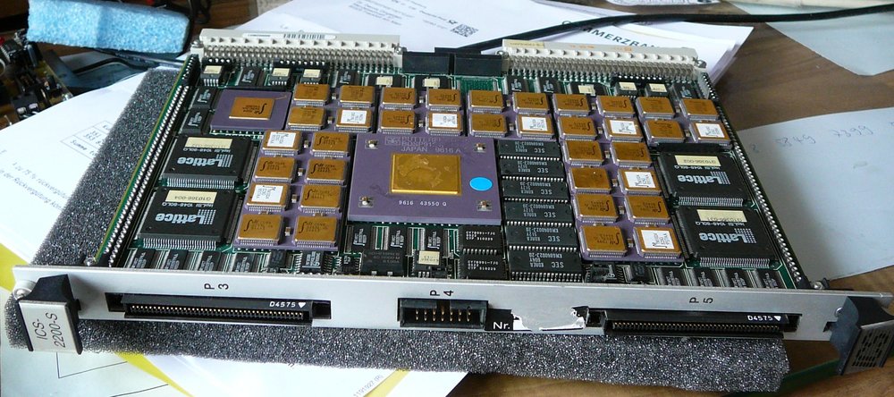
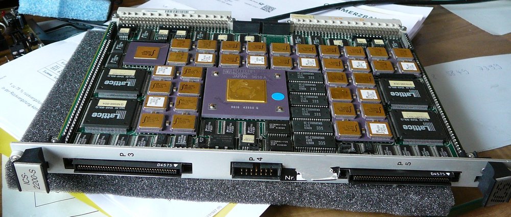
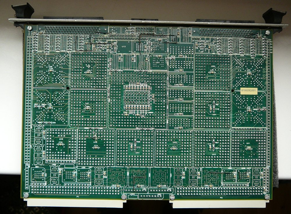
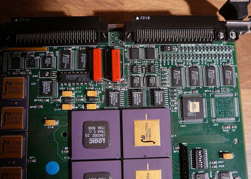
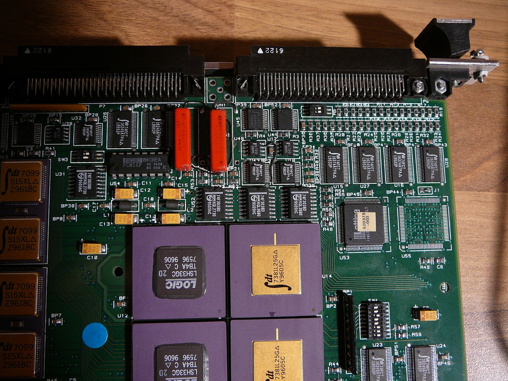
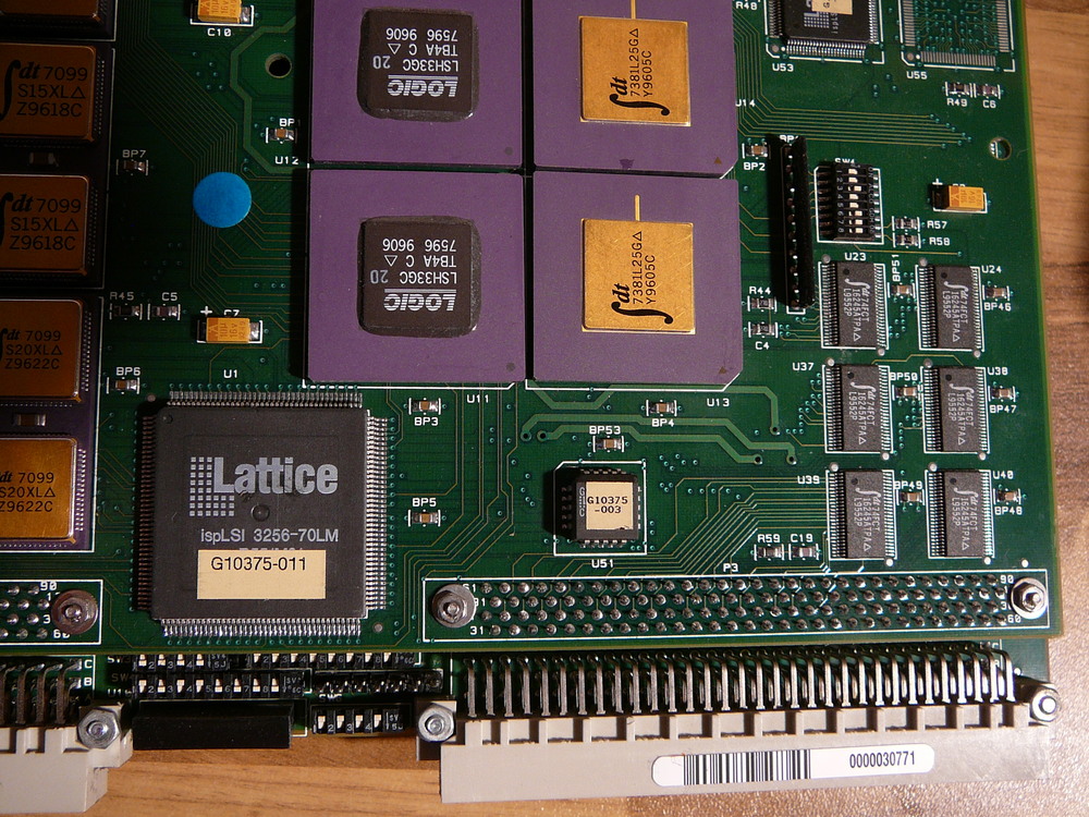
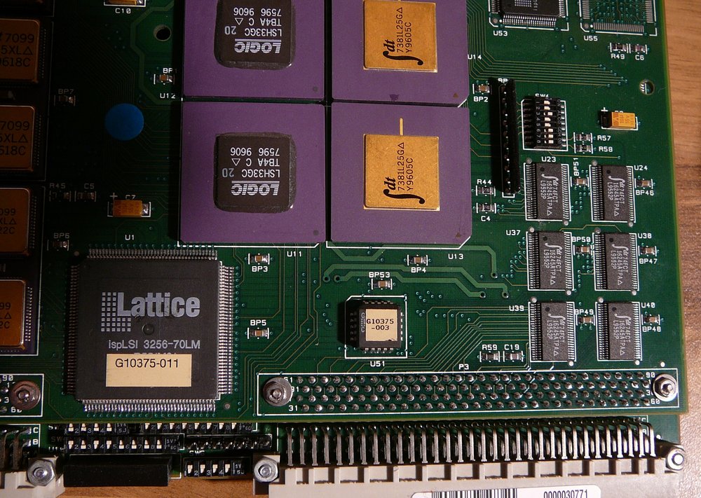
ICS-2200S
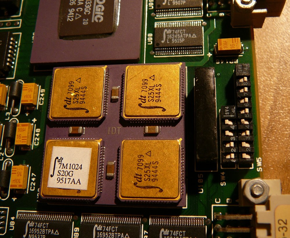
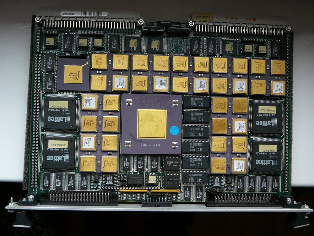
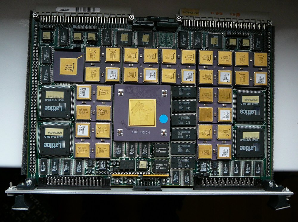
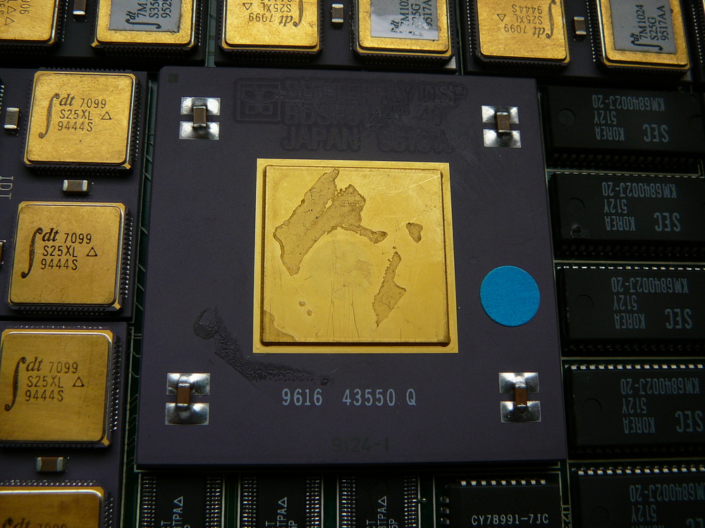
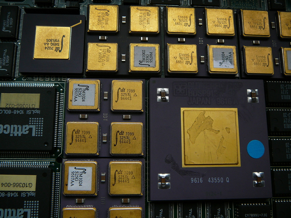
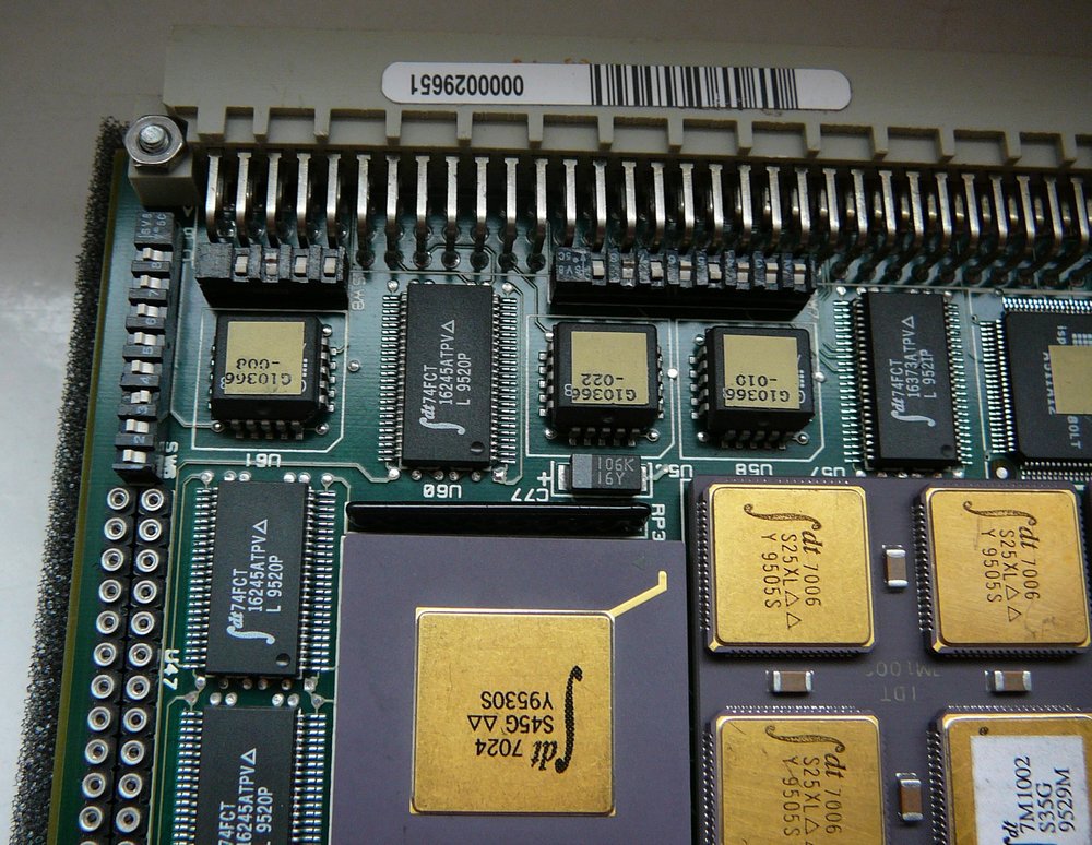
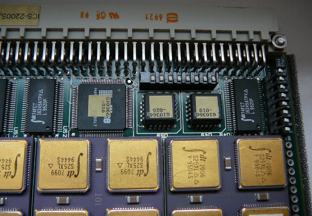
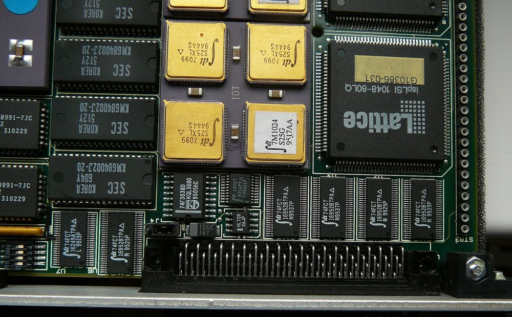
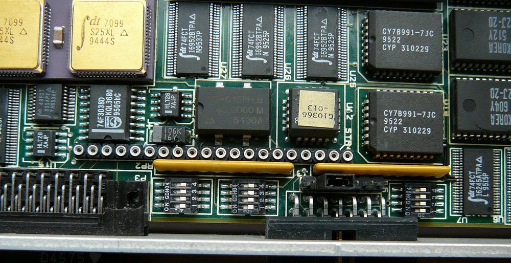
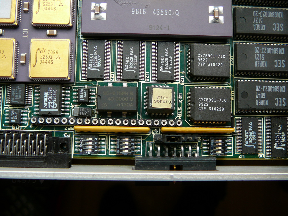
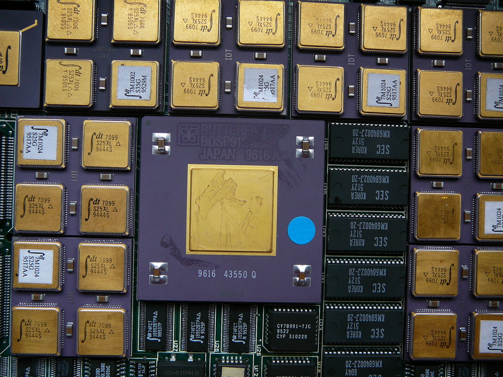
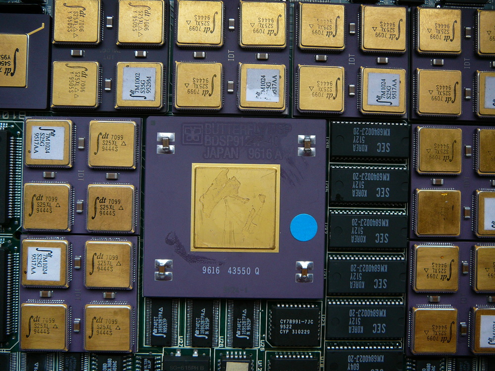
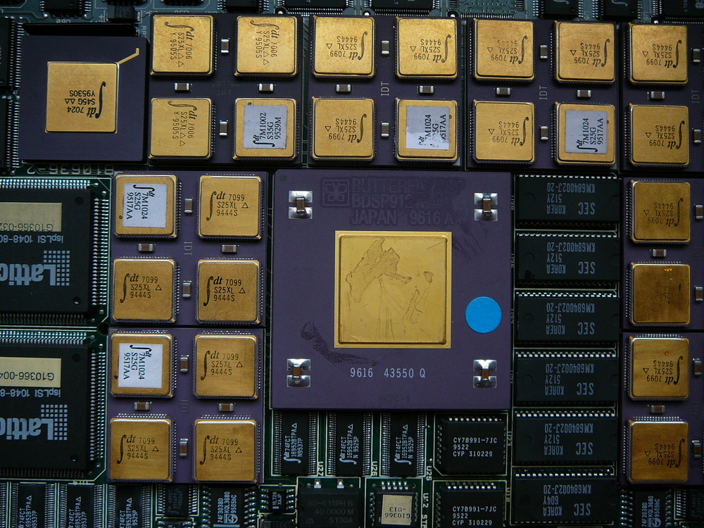
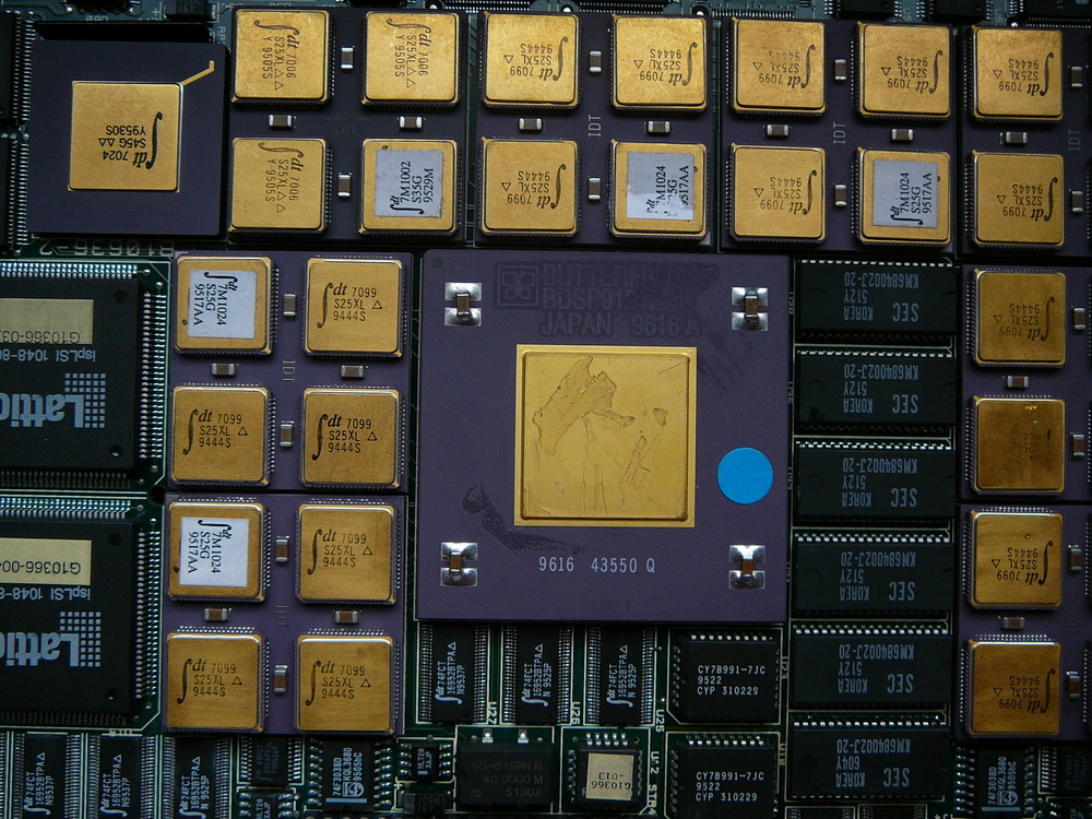
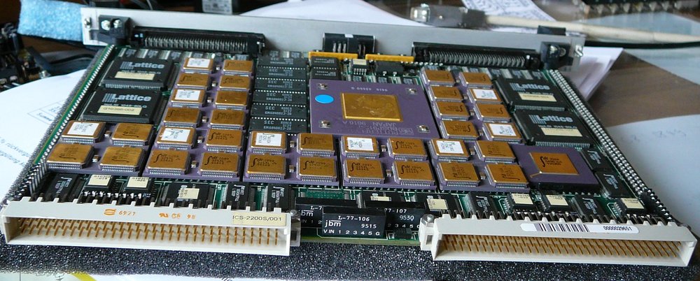
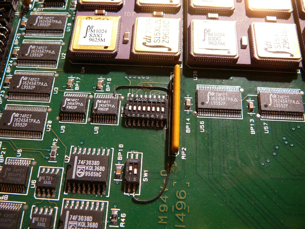
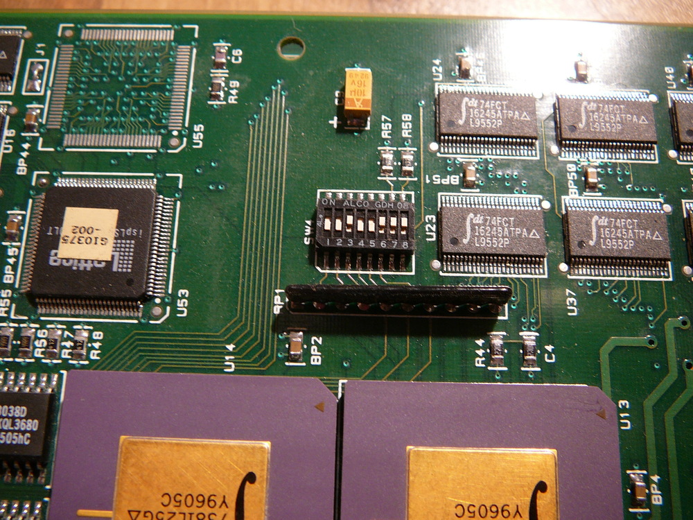
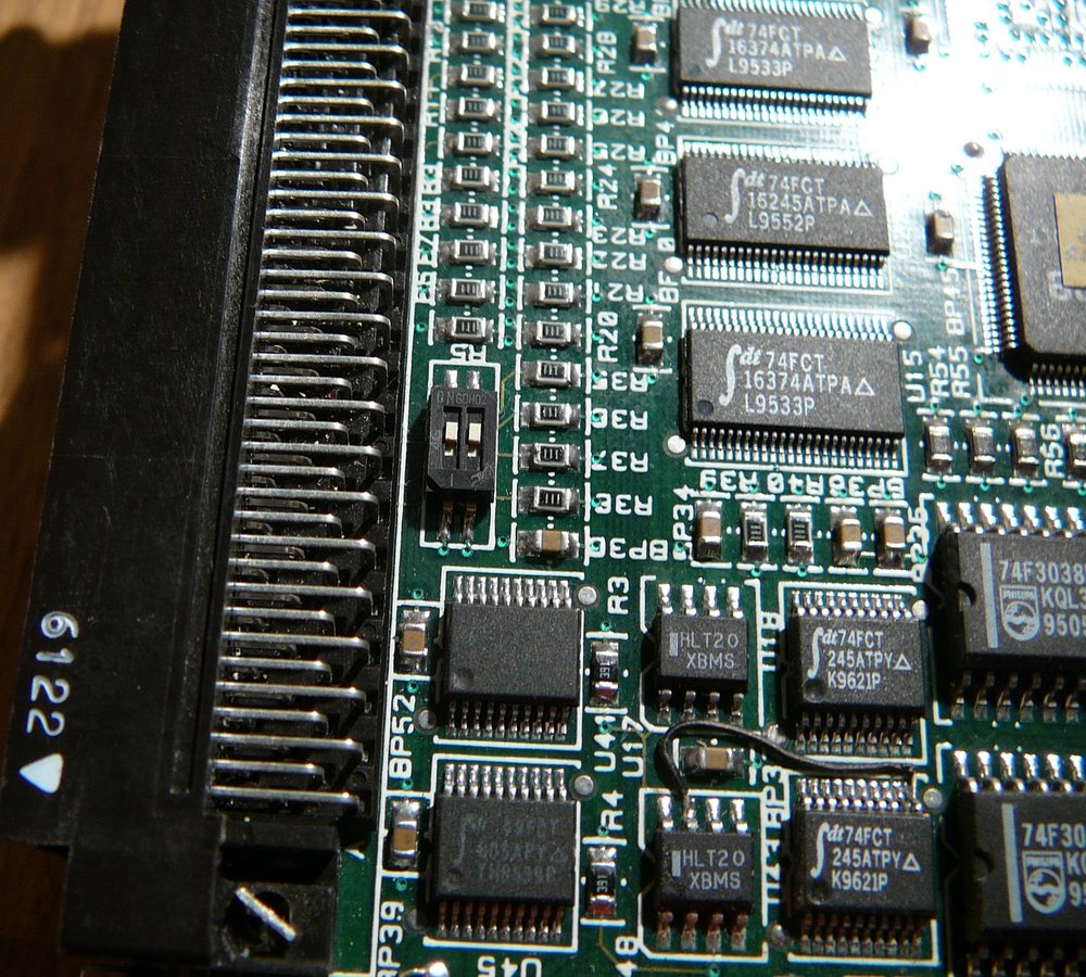
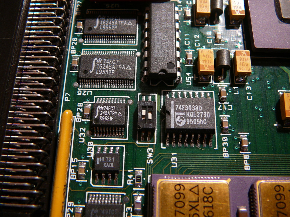
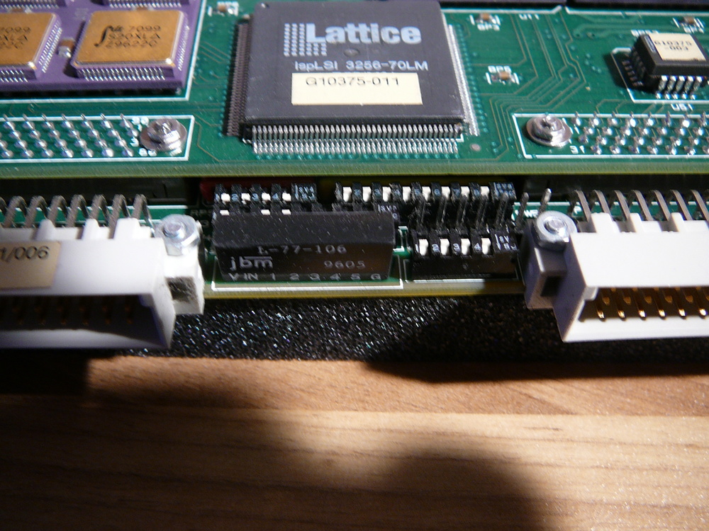
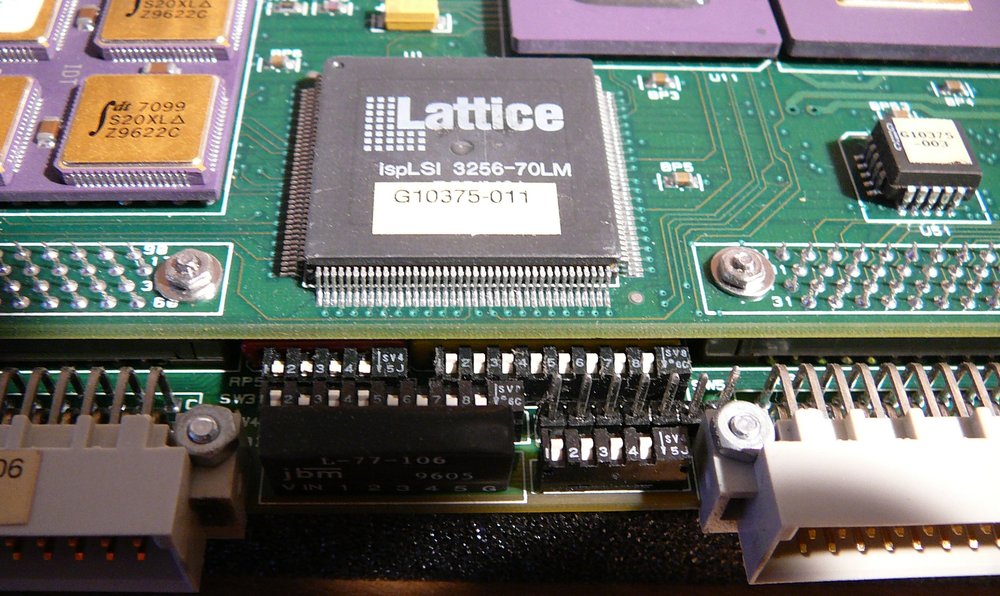
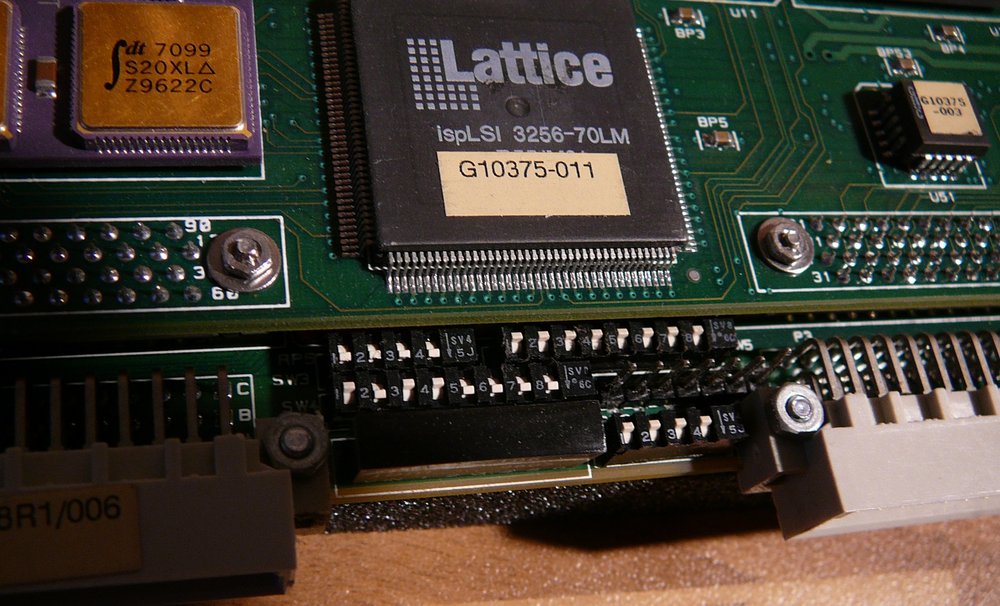
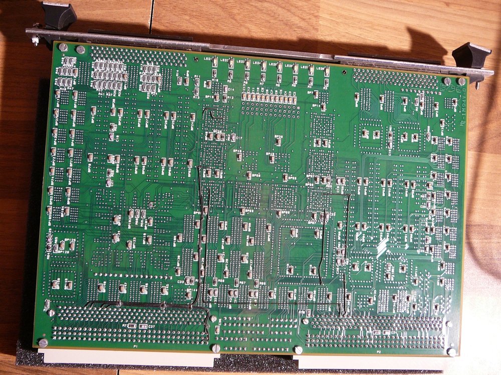
The ICS-2200 board is dominated by a big Butterfly DSP BDSP9124, a chip designed by Sharp/Butterfly. Around that chip, 9 other gold-plated chips are arranged. Moreover there are 4 big Lattice FPGAs and one other big gold-plated chip on the board. 6 SRAM chips can also be seen.
Gold-plated chips: 2x dt7006 S25XL Y 9505S with sticker 7M1002 S35G 9529M 7x dt7099 S25XL Y 9444S with sticker 7M1024 S25G 9517AA
Lattice FPGAs 4x ispLSI 1048-80Q where 95xx und 94xx are date codes (1994 und 1995 er Chips)
RAM SEC KM684002J-20, this is 512Kx8 bit SRAM, this means the board has 3MB RAM.
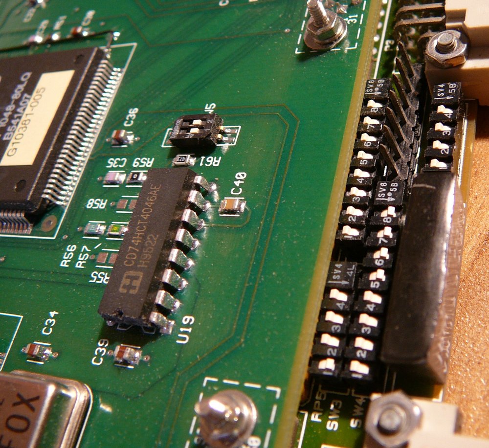
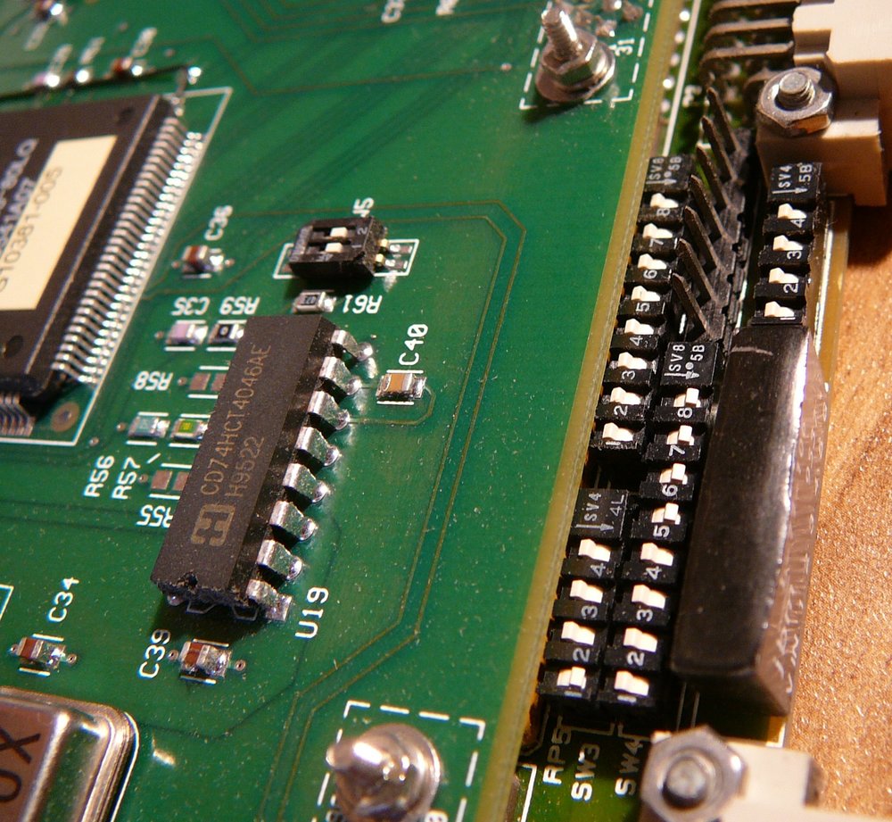
At the front of the board, three connectors are located. P3, P4, P5.


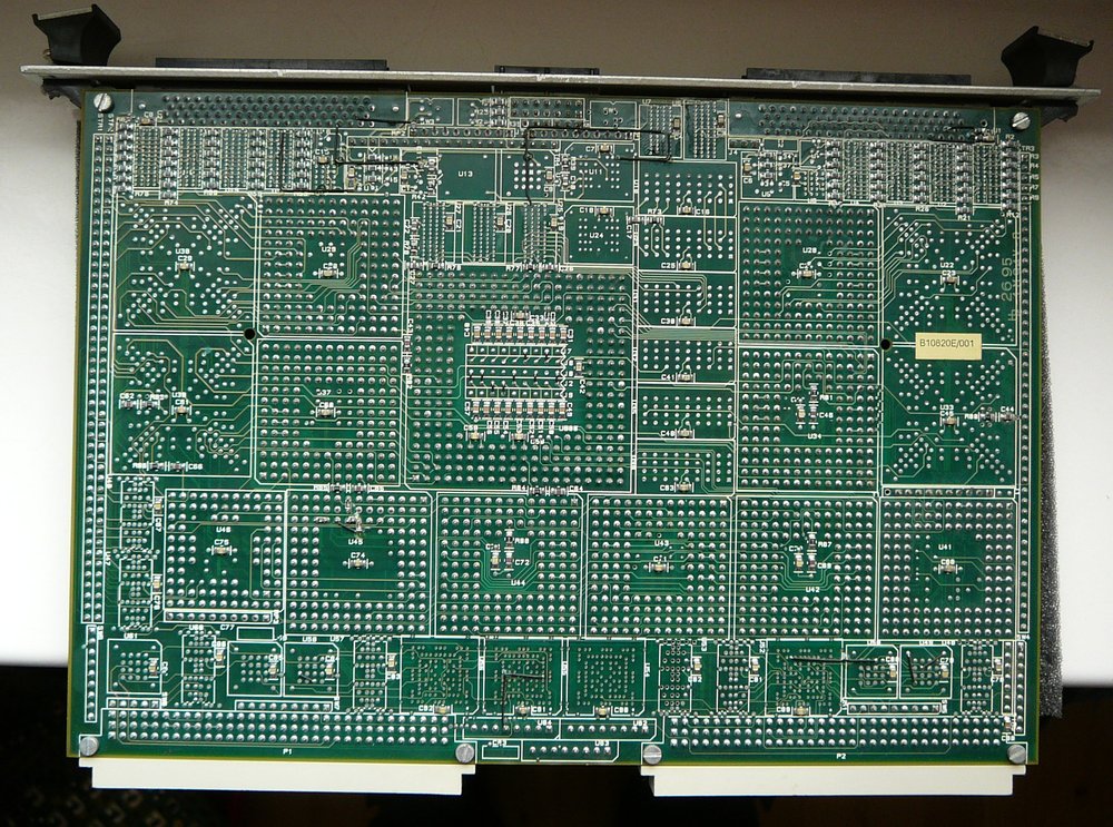
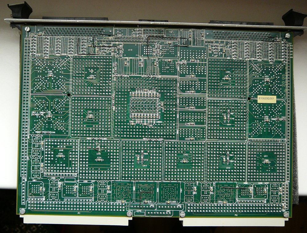
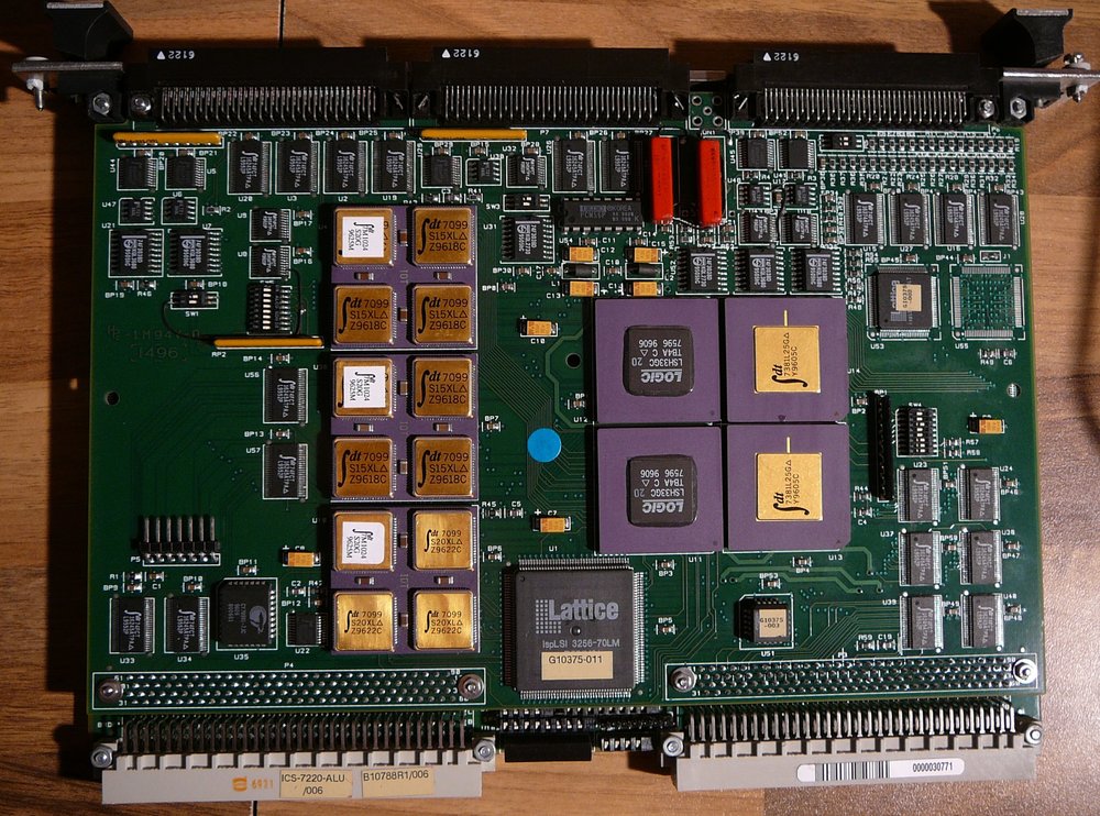
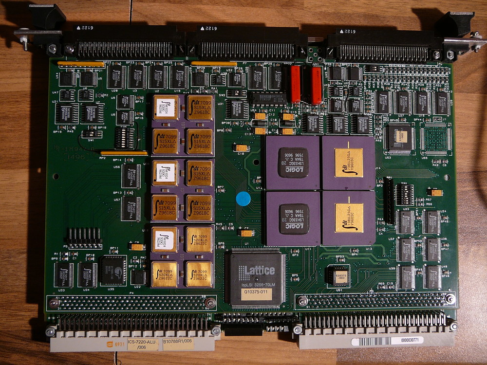

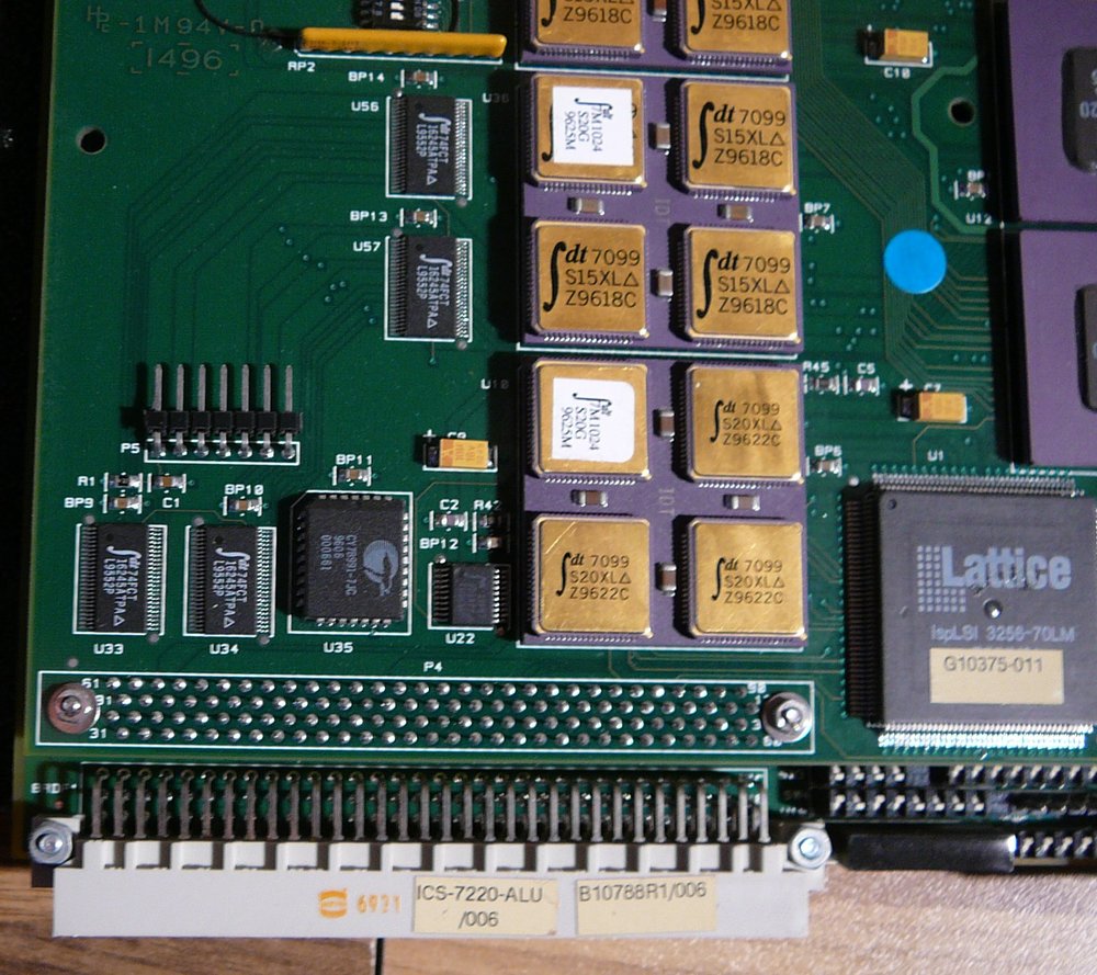
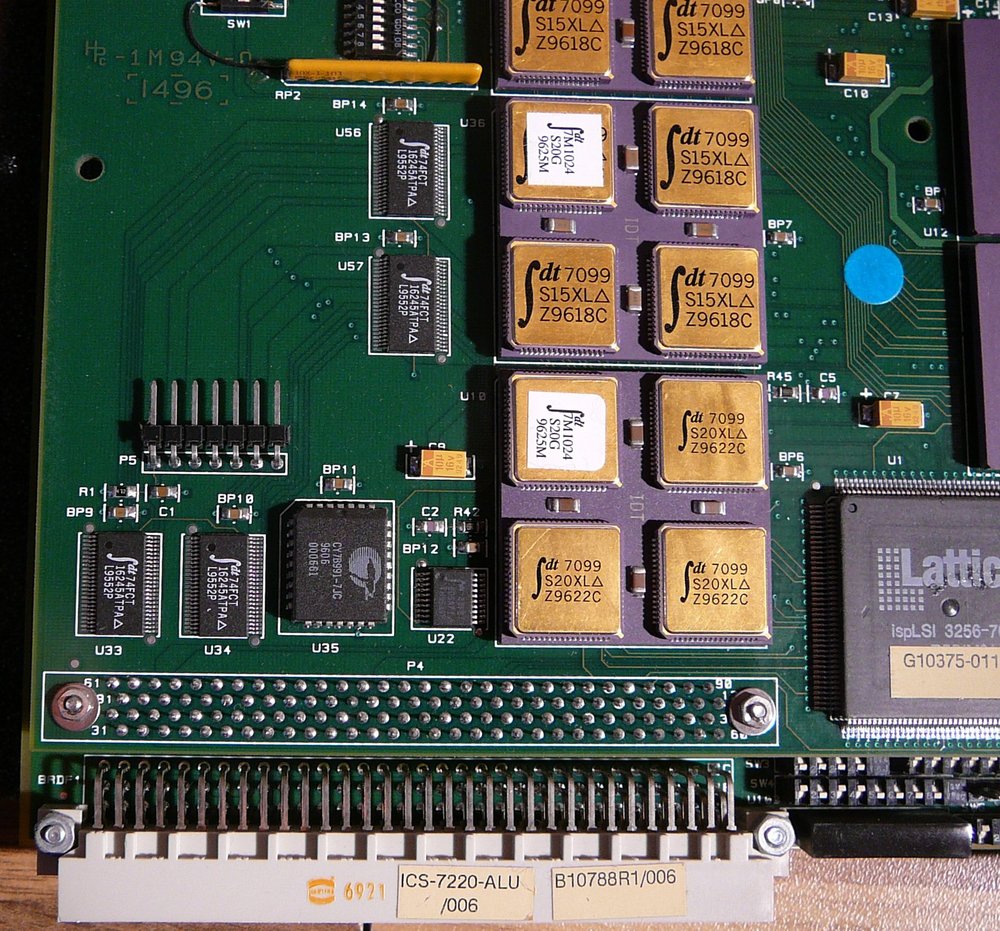
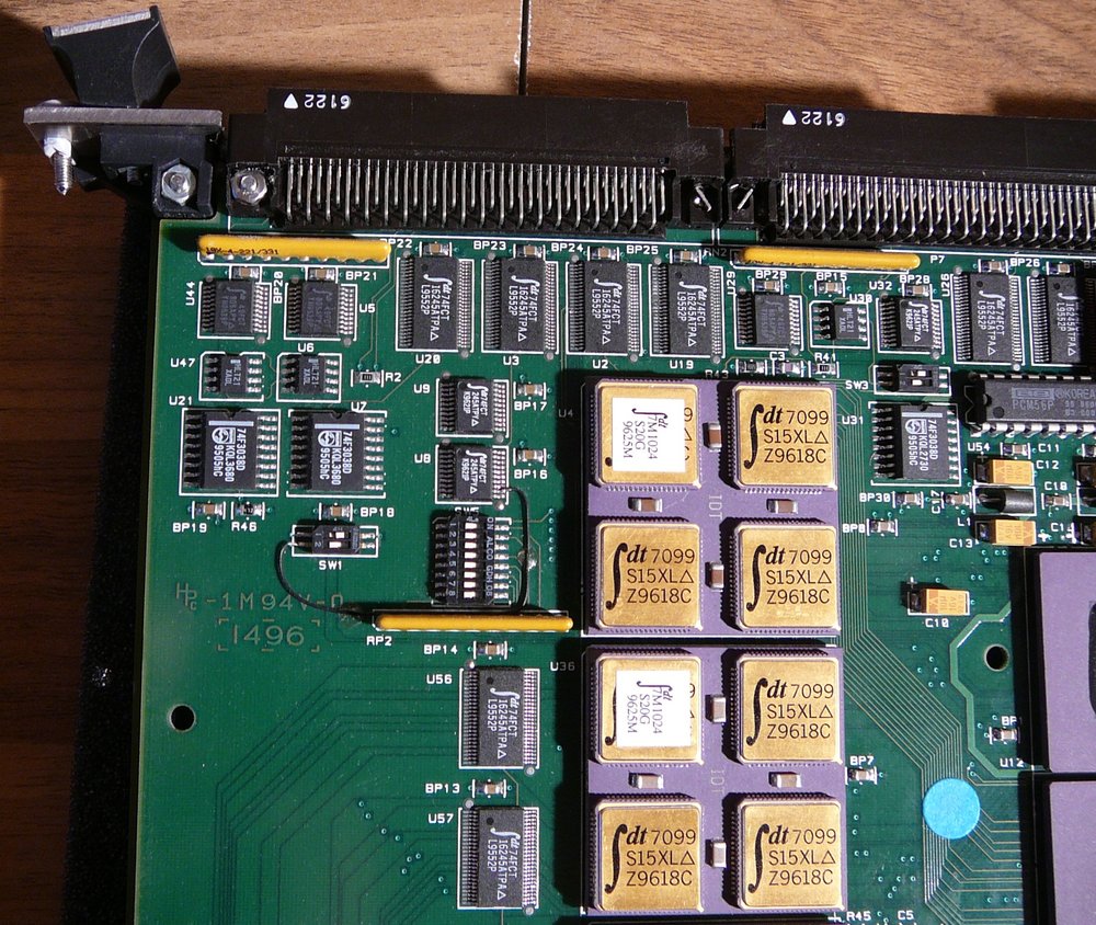
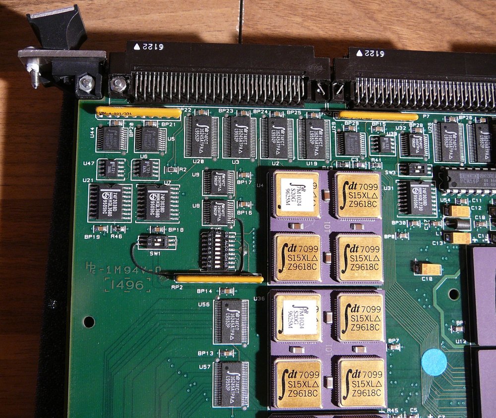
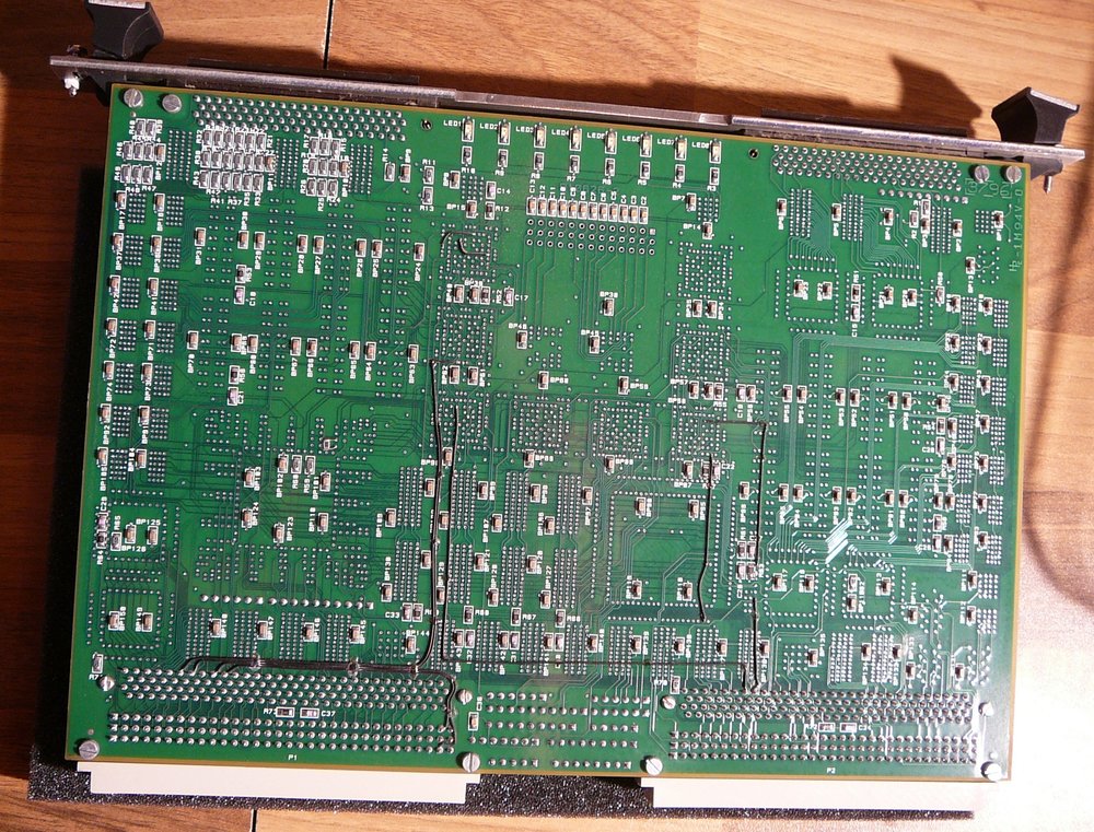
ICS-7220 ALU


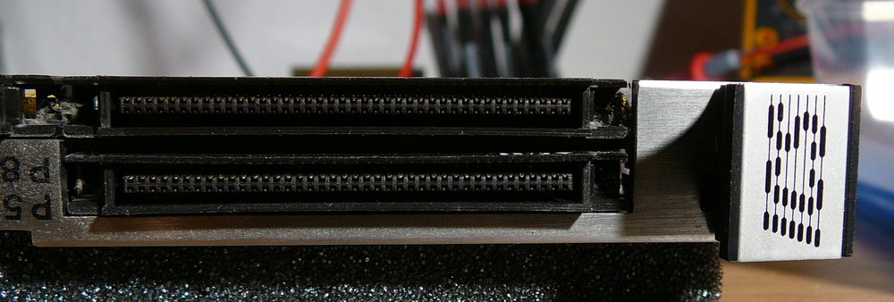

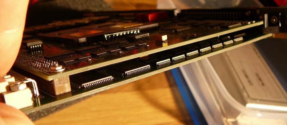
Battery

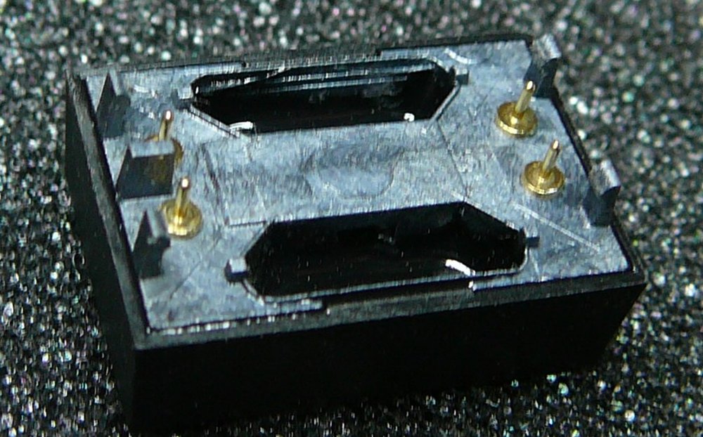
ICS-7220 DxR

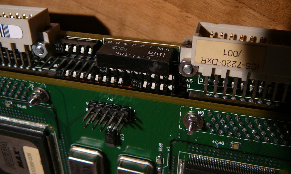
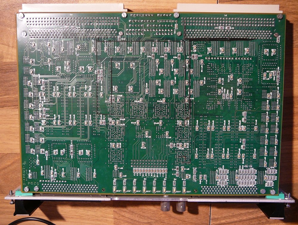
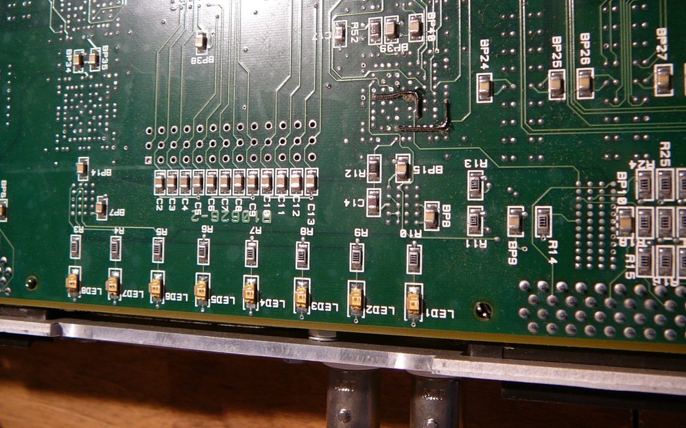
ICS-7220 SBFA
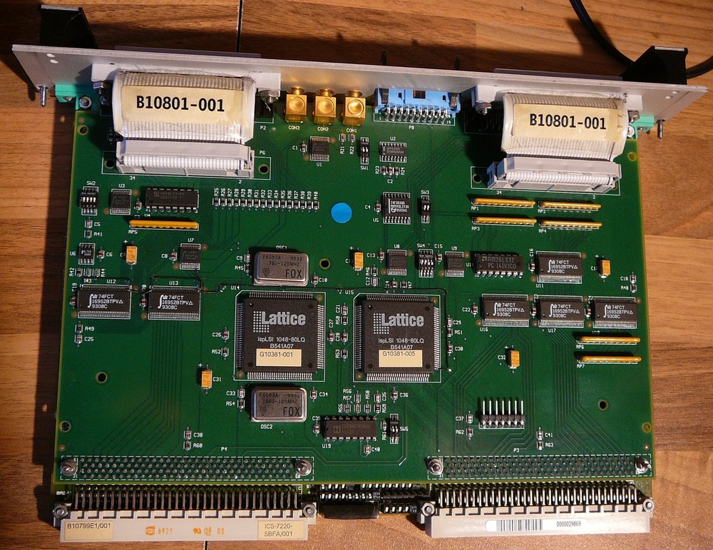


Attempt to revive the ICS-1000
Zusammenhang
Die CPU-Karte muß immer im ersten Slot stecken. Von dort bekommt sie Strom etc. Mit dem Backplane ist die Karte über zwei Stecker verbunden, Einer der beiden Stecker trägt alle Signale, die nach draussen gehen. Diese werden über einen Adapter (“P2”) auf ein “Transition Board” geroutet. Dieses bildet die Bus-Signale auf Stecker ab für Seriell, Parallel, SCSI, LAN, …
Nach dem Einschalten des Geräts blinkt ein Cursor ("_"), sonst passiert nichts. Wird der RESET-Button am CPU-Board gedrückt, kommt pro Drücken ein “#” Zeichen auf den Bildschirm. Sonst kommt nichts und auch Eingabeversuche am Touchpanel haben keinen Effekt. Das CPU-Board hat bis zu 4 serielle Anschlüße, der erste ist die Systemkonsole, ich vermute dass das VFD nicht an der Console angeschlossen ist, sondern m rückseitigen Terminal-Anschluß,
Es wird übrigens auch nicht versucht von der HD zu booten. Auch die Floppy leuchtet nicht kurz auf. Die HD initialisiert sich (hört man), dann passiert nichts mehr.
Check with PEP Display: it is ok, RS232 parameters are 9800 8N1. Note that the PEP is connected to its serial connector via a Nullmodem adapter.
After attaching the PC with a Nullmodem-Adapter to the “Terminal-Connector” at the back of the device, I can read the start of the boot process!
It says that it cannot access a boot device and goes to a vxWorks boot prompt. Checking the Internet regarding vxWorks booting, I issued the command “c” and " p" to get the current parameters set.
[VxWorks Boot]: c '.' = clear field; '-' = go to previous field; ^D = quit boot device : ATAGTDPPQ?T??G????&0 processor number : 0 host name : file name : inet on ethernet (e) : inet on backplane (b): host inet (h) : gateway inet (g) : user (u) : ftp password (pw) (blank = use rsh): flags (f) : 0x0 target name (tn) : startup script (s) : other (o) : [VxWorks Boot]: [VxWorks Boot]: ? ? - print this list @ - boot (load and go) p - print boot params c - change boot params l - load boot file g adrs - go to adrs d adrs [,n] - display memory m adrs - modify memory f adrs, nbytes, value - fill memory t adrs, adrs, nbytes - copy memory e - print fatal exception n netif - print network interface device address $dev(0,procnum)host:/file h=# e=# b=# g=# u=usr [pw=passwd] f=# tn=targetname s=script o=other boot device: scsi=id,lun file name: /sd0/vxWorks Boot flags: 0x02 - load local system symbols 0x04 - don't autoboot 0x08 - quick autoboot (no countdown) 0x20 - disable login security 0x40 - use bootp to get boot parameters 0x80 - use tftp to get boot image 0x100 - use proxy arp available boot devices: dc bp sm scsi
Because the NVRAM buffer battery is defect, the data in NVRAM is nonsense and must be entered manually. But what values are correct?
Boot devices:
dc = Ethernet scsi : SCSI of course bp: ??? (backplane?) sm: ??? (floppy?)
After tring around, I found that the boot device must be named
scsi=0,0
Then the disk is accessed (I can hear the drive heads move :-). Now I tried to figure out the file name (name of kernel image, usually vxWorks). I got different error messages
error loading file: status = 0x610001. = file not found tError
loading file: errno = 0x37000b. -> LUN not present Error loading file: errno = 0x370001. -> target not ready (disk gibts nicht)
Hm. After trying everything whih may be working, no process. So I need to read the harddisk content. This is not possible via boot prompt. In my linux PC, there is still a SCSI controller built in, it has a 50 pin iternal connector. So I took the harddrive SCSI cable from the transition module and connected it to my PCs SCSI adapter. First switching on the ICS-1000 gives power to the drive, and after initializing I switched on my PC. And tada, Linux detects the harddisk (by the way, the floppy drive WSC SLS-120 is also detected).
...
[ 3.600580] ahc_pci:5:1:0: Host Adapter Bios disabled. Using default SCSI device parameters

[ 18.603151] scsi10 : Adaptec AIC7XXX EISA/VLB/PCI SCSI HBA DRIVER, Rev 7.0
[ 18.603153] <Adaptec 2902/04/10/15/20C/30C SCSI adapter>
[ 18.603155] aic7850: Single Channel A, SCSI Id=7, 3/253 SCBs
[ 18.603156]
[ 18.732716] scsi 10:0:0:0: Direct-Access NEC DSE2100S 0306 PQ: 0 ANSI: 2 CCS
[ 18.732729] scsi target10:0:0: Beginning Domain Validation
[ 18.735414] scsi target10:0:0: FAST-10 SCSI 10.0 MB/s ST (100 ns, offset 15)
[ 18.737189] scsi target10:0:0: Domain Validation skipping write tests
[ 18.737192] scsi target10:0:0: Ending Domain Validation
[ 18.739561] sd 10:0:0:0:  [sdc] 4124736 512-byte logical blocks: (2.11 GB/1.96 GiB)
[ 18.740015] sd 10:0:0:0:  [sdc] Write Protect is off
[ 18.740020] sd 10:0:0:0:  [sdc] Mode Sense: 6f 00 00 08
[ 18.740994] sd 10:0:0:0:  [sdc] Write cache: enabled, read cache: enabled, doesn't support DPO or FUA
[ 18.751993] sdc:
[ 18.754834] sd 10:0:0:0:  [sdc] Attached SCSI disk
[ 18.759352] scsi 10:0:1:0: Direct-Access WSC SLS-120 7.30 PQ: 0 ANSI: 2
[ 18.759364] scsi target10:0:1: Beginning Domain Validation
[ 18.770478] scsi target10:0:1: FAST-10 SCSI 10.0 MB/s ST (100 ns, offset 15)
[ 18.778124] scsi target10:0:1: Domain Validation skipping write tests
[ 18.778127] scsi target10:0:1: Ending Domain Validation
[ 18.787341] sd 10:0:1:0:  [sdd] Attached SCSI removable disk
[ 18.796494] scsi scan: INQUIRY result too short (5), using 36
[ 20.117413] hp_sw: device handler registered
[ 20.119470] alua: device handler registered ...
It is not possible to mount it, because it has an unknown filesystem on it. But I was able to make a bytecopy of the complete 2GB harddisk with the dd command:
socraggio:/home/dennis/ics1000 # dd if=/dev/sdc of=disk-image.img 4124736+0 Datensätze ein 4124736+0 Datensätze aus 2111864832 Bytes (2,1 GB) kopiert, 411,103 s, 5,1 MB/s
So the harddrive seems ok. I hope that the data on it was not deleted by someone and that the VxWorks installation is still on the harddisk…
Then I tried around with bvi (binary vi) and found that the drive has filesystem type “VXEXT1.0”. This is Wind River propietary, some special extension of old dos file system. The data below must e.g. be a directory structure…
... 00040200 76 77 20 20 20 20 20 20 20 20 20 20 20 20 20 20 20 20 20 20 20 20 20 20 vw 00040218 20 20 20 20 20 20 20 20 20 20 20 20 20 20 20 20 00 00 FF FF 00 00 00 00 ........ 00040230 00 00 00 00 00 10 00 00 21 00 02 00 00 00 00 00 78 66 69 6C 65 73 20 20 ........!.......xfiles 00040248 20 20 20 20 20 20 20 20 20 20 20 20 20 20 20 20 20 20 20 20 20 20 20 20 00040260 20 20 20 20 20 20 20 20 00 00 FF FF 00 00 00 00 00 00 00 00 00 10 00 00 ................ 00040278 21 00 03 00 00 00 00 00 73 74 61 72 74 75 70 2E 65 78 65 20 20 20 20 20 !.......startup.exe 00040290 20 20 20 20 20 20 20 20 20 20 20 20 20 20 20 20 20 20 20 20 20 20 20 20 000402A8 00 00 FF FF 00 00 00 00 00 00 00 00 00 20 00 00 21 00 1E 00 FF C5 02 00 ............. ..!....... 000402C0 74 77 69 6E 36 61 20 20 20 20 20 20 20 20 20 20 20 20 20 20 20 20 20 20 twin6a 000402D8 20 20 20 20 20 20 20 20 20 20 20 20 20 20 20 20 00 00 FF FF 00 00 00 00 ........ 000402F0 00 00 00 00 00 10 00 00 21 00 21 00 00 00 00 00 73 79 73 65 78 74 2E 65 ........!.!.....sysext.e 00040308 78 65 20 20 20 20 20 20 20 20 20 20 20 20 20 20 20 20 20 20 20 20 20 20 xe 00040320 20 20 20 20 20 20 20 20 00 00 FF FF 00 00 00 00 00 00 00 00 00 20 00 00 ............. .. 00040338 21 00 22 00 E3 F7 00 00 73 70 61 77 6E 2E 65 78 65 20 20 20 20 20 20 20 !.".....spawn.exe 00040350 20 20 20 20 20 20 20 20 20 20 20 20 20 20 20 20 20 20 20 20 20 20 20 20 00040368 00 00 FF FF 00 00 00 00 00 00 00 00 00 20 00 00 21 00 23 00 3D 6C 00 00 ............. ..!.#.=l.. 00040380 6D 65 6E 75 64 72 69 76 2E 65 78 65 20 20 20 20 20 20 20 20 20 20 20 20 menudriv.exe 00040398 20 20 20 20 20 20 20 20 20 20 20 20 20 20 20 20 00 00 FF FF 00 00 00 00 ........ 000403B0 00 00 00 00 00 20 00 00 21 00 24 00 B5 77 00 00 66 6C 69 70 64 72 69 76 ..... ..!.$..w..flipdriv 000403C8 2E 65 78 65 20 20 20 20 20 20 20 20 20 20 20 20 20 20 20 20 20 20 20 20 .exe ... Just by looking at the byte strings I could not find out the name of the vxWorks kernel image. So I made a web search and found that there is a linux driver for the VXEXT file system.
This requires compiling a kernel module for this file system.
A short try with the current version of the VXEXT driver on OpenSuse 12.2 which uses Linux Kernel 3.4 fails. The VXEXT driver is a little bit outdated. I succeeded compiling it on a VM with OpenSuse 11.3 which uses Linux kernel 2.6.x . I needed to change in one file (misc.c) some 64-bit division (I was using a 32-bit Linux system which gave an unresolved symbol for the kernel module). After that, It was a trivial task to mount the disk image created with the dd-command some days ago. I used the linux feature of mounting a file as a loopback device.
mount -t vtext -o loop disk-image.img /mnt2
So I was able to examine the content of the harddisk. I found that the vxWorks kernel “vxworks.st” was located in a directory “vw” on the disk. But this was not the complete solution… I found out that the argument “file name” at the vxWorks boot prompt was not only the file name itself ("/vw/vxworks.st") but also included the boot device: “/scsi=0,0/vw/vxworks.st” .
This leads me to the first sucessful boot:
boot device : scsi=0,00 processor number : 0 host name : ics file name : /vw/vxworks.st /scsi=0,0/vw/vxworks.st
inet on ethernet (e) : 192.168.178.100
inet on backplane (b):
host inet (h) :
gateway inet (g) : 192.168.178.1
user (u) :
ftp password (pw) (blank = use rsh):
flags (f) : 0x0
target name (tn) :
startup script (s) : startup.scr
other (o) :
[VxWorks Boot]:
[VxWorks Boot]: @ boot device : scsi=0,0 unit number : 0 processor number : 0 host name : ics file name : /scsi=0,0/vw/vxworks.st
inet on ethernet (e) : 192.168.178.100
gateway inet (g) : 192.168.178.1
flags (f) : 0x0
startup script (s) : startup.scr
1510608 Starting at 0x100000... mounting tape drive scsiPhysDevCreate for tape device failed.
Auto-configuring SCSI bus...
ID LUN VendorID ProductID Rev. Type Blocks BlkSize pScsiPhysDev
-- --- -------- ---------------- ---- ---- -------- ------- ------------
0 0 NEC DSE2100S 0306 0 4124736 512 0x017f7720
mounting SLS-120 floppy drive mounting hard drive
Target Name: vx
Target User: target
Attaching network interface lo0.. done.
NFS client support not included.
Adding 3588 symbols for standalone.
shell is included
CPU: Motorola MVME2600 - MPC 604e.
Processor #0. Memory Size: 0x2000000. BSP version 1.1/4. WDB: Ready.
# Interactive Circuits And Systems Ltd SYSTEM-1000
# Unable to open startup script startup.scr
I was not able to ping the machine after boot. I am still do not know what to enter for all these different IP adresses…
There is a startup-Script on the harddik, which is a text file. But I noted at the first boot, that the path would need also a leading “/scsi=0,0”…
There is some new information, e.g. the RAM size is 32MB (0x2000000) and the processor is a MPC604e. The vxWorks version is 5.3.1.
\-> version VxWorks (for Motorola MVME2600 - MPC 604e) version 5.3.1. Kernel: WIND version
2.5. Made on Jul 24 2001, 13:45:51. Boot line: scsi=0,0(0,0)ics:/scsi=0,0/vw/vxworks.st
e=192.168.178.100 g=192.168.178.1 s=startup.scr value = 100 = 0x64 = 'd'
Finally the NVRAM buffer battery came in and i replaced it. As expected, the boot parameters are now persisted.
Next step was to setup the network. After some reading I understand that the network hardware must be initialized during booting. To do that, you need to add the name of the network device to the “other” parameter of the boot parameters. After trying around, I succeeded with the name “dc”.
The network device can be probed at the boot prompt with the netif ccommand.
n netif               - print network interface device address

[VxWorks Boot]: n dc Address for device "dc0" == 08:00:3e:2a:f9:38
The booting now includes also the network:
[VxWorks Boot]: @ boot device : scsi=0,0 unit number : 0 processor number : 0 host name : ics1 file name : /scsi=0,0/vw/vxworks.st inet on ethernet (e) : 192.168.178.100 host inet (h) : 192.168.178.100 gateway inet (g) : 192.168.178.1 flags (f) : 0x0 target name (tn) : ics startup script (s) : startup.scr other (o) : dc 1510608 Starting at 0x100000... mounting tape drive scsiPhysDevCreate for tape device failed. Auto-configuring SCSI bus... ID LUN VendorID ProductID Rev. Type Blocks BlkSize pScsiPhysDev -- --- -------- ---------------- ---- ---- -------- ------- ------------ 0 0 NEC DSE2100S 0306 0 4124736 512 0x017f7720 mounting SLS-120 floppy drive mounting hard drive User: targetAttaching network interface dc0.. done. Attaching network interface lo0.. done. NFS client support not included. Adding 3588 symbols for standalone. shell is included CPU: Motorola MVME2600 - MPC 604e. Processor #0. Memory Size: 0x2000000. BSP version 1.1/4. WDB: Ready. Interactive Circuits And Systems Ltd SYSTEM-1000 Unable to open startup script startup.scr
Some more information can be gathered now from vxWorks
\-> ifShow dc (unit number 0): Flags: (0x63) UP BROADCAST ARP RUNNING Type: ETHERNET_CSMACD Internet address: 192.168.178.100 Broadcast address: 192.168.178.255 Netmask 0xffffff00 Subnetmask 0xffffff00 Ethernet address is 08:00:3e:2a:f9:38 Metric is 0 Maximum Transfer Unit size is 1500 0 packets received; 0 packets sent 0 multicast packets received 0 multicast packets sent 0 input errors; 0 output errors 0 collisions; 0 dropped lo (unit number 0): Flags: (0x8069) UP LOOPBACK MULTICAST ARP RUNNING Type: SOFTWARE_LOOPBACK Internet address: 127.0.0.1 Netmask 0xff000000 Subnetmask 0xff000000 Metric is 0 Maximum Transfer Unit size is 32768 12 packets received; 12 packets sent 0 multicast packets received 0 multicast packets sent 0 input errors; 0 output errors 0 collisions; 0 dropped value = 29 = 0x1d -> routeShow ROUTE NET TABLE destination gateway flags Refcnt Use Interface ---------------------------------------------------------------------------- 192.168.178.0 192.168.178.1 3 1 15 dc0 ---------------------------------------------------------------------------- ROUTE HOST TABLE destination gateway flags Refcnt Use Interface ---------------------------------------------------------------------------- 127.0.0.1 127.0.0.1 5 1 0 lo0 ---------------------------------------------------------------------------- value = 77 = 0x4d = 'M'
I found that CRTL-X immediately reboots the machine. No need to switch it off and on again and again.
Now I fumbled around with all these IP adresses and came up with the following parameters which are perfect:
boot device : scsi=0,0 unit number : 0 processor number : 0 host name : soc file name : /scsi=0,0/vw/vxworks.st
inet on ethernet (e) : 192.168.178.100 flags (f) : 0x0 target name (tn) :
ics startup script (s) : startup.scr other (o) : dc
Finally I also found out how to access the harddisk :-) cd “D:” and the D needs to be capital letter…
The content of the startup script is
# startup script ld < startup.exe startUp routeAdd("136.1.0.0","192.9.211.250")
sp(flip)
This means that some callable functions are loaded (“ld <…”) and one of those functions is called (“startUp”). A static route is added and finally there is a task switch.
For some unknown reason, the startup script is found but not executed. If I execute the commands manually, everything is fine. This means that all the card drivers are loaded into memory and a controlling text application screen occurs on the built in display of the machine. There, clusters can be defined and controlled, machine parameters can be changed and data and configurations can be saved and loaded. Very nice.
I found that the machine runs a telnet and a ftp server which can be accessed anonymously and by user account.
To go on, I needed more knowhow regarding vxWorks, PowerPC executable and assembler and the original purpose of the device.
vXWorks random information
The way an executable is started in vxWorks is somehow funny. You can load a binary file (an exe) into memory. It is not immediately executed like when loading an executable in linux or windows, it just stays in memory., but all external accessible symbols (non-static C functions etc.) are accessible. There is no main symbol but all accessible symbols can be called just by entering their name at command line. So loading the “startup.exe” loads all symbols (and code) for that binary, and you need to know the entry C function to call. For the example, this function is named “startUp”. After being loaded into memory, a binary is named a “task”. Several commands can be executed on a task:
i - prints task info td - ends task (use task name or task id)
Add an environment variable:
putenv “DISPLAY=192.168.178.22:0”
Display the environment: envShow
> envShow (global environment) 0: D:/xfiles 1: USE_LOCAL_FS 2: XKEYSYMDB=D:/xfiles/lib/xkeysym.db 3: DISPLAY=192.168.178.22:0 value = 28 = 0x1c
Further vxWorks commands:
- ls,ll pwd adr
- SpaceShow(details 0, 1) - Show details of the Address Space, including physical address, User region address and kernel virtual mapping.
- envShow(taskId) - Show environment for a given task
- iosDevShow Show loaded I/O Devices
- iosDrvShow - Show I/O Device Driver Function Table
- iosFdShow - show open File Descriptors
- memShow - show memory usage statistics
- moduleShow - show downloaded modules
- objShowAll - show the list of all the objects in the system (semaphores, tasks, msgQs, etc…)
- objShow (objectId) - show detailed information about an object share
Use the ICS-1000 system
After trying around, I was able to start the x windows programs in the directory “xfiles”.
putenv "DISPLAY=192.168.178.22:0"
cd "D:"
ld <startup.exe
cd "xfiles"
ld <xmain
startGUI
Precodition on X Server: YasT Security tab (preferred because this works) or below:
DISPLAYMANAGER_REMOTE_ACCESS="yes"
DISPLAYMANAGER_XSERVER_TCP_PORT_6000_OPEN="yes"
in /etc/sysconfig/displaymanager and don’t forget the xhost +.
xhost+ must be installed from Yast since
OpenSuse 13.2. Check if XServer listens on port 6000:
netstat -anp | grep 600
It gives some text output but more interesting, the x window output on my linux machine. The GUIs are from mid 1990s and do look poor, but they work. This seems to be an early OSF/Motif based GUI.
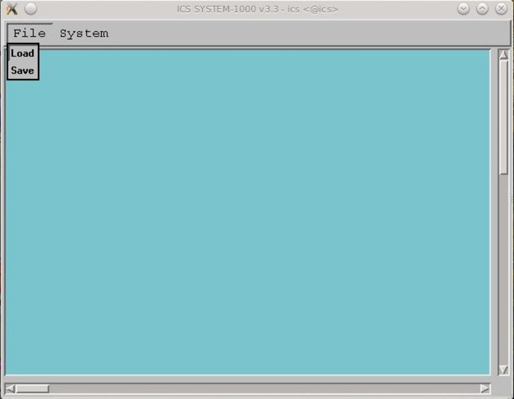
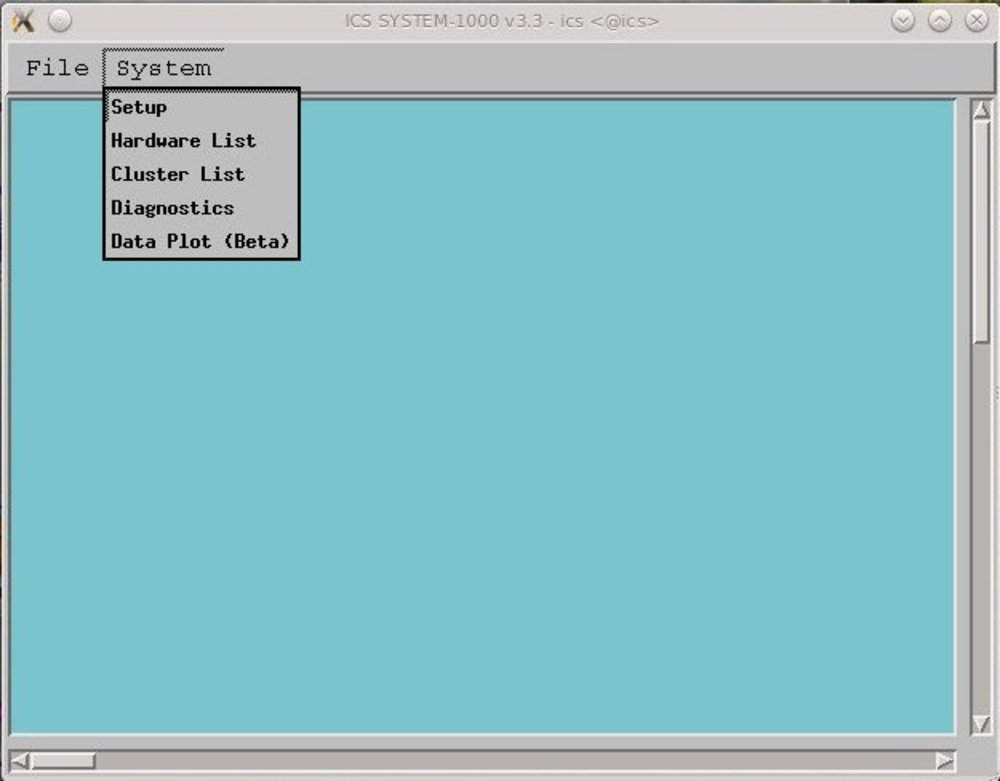
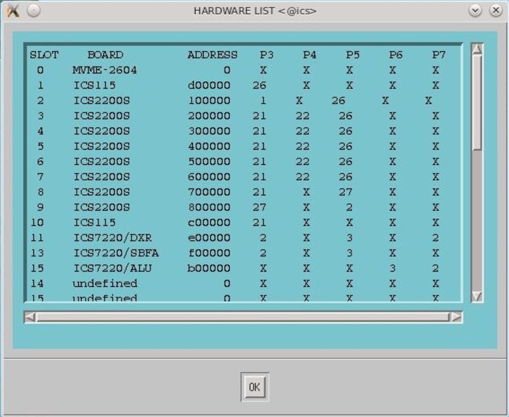
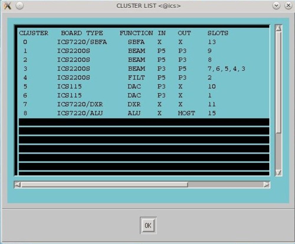
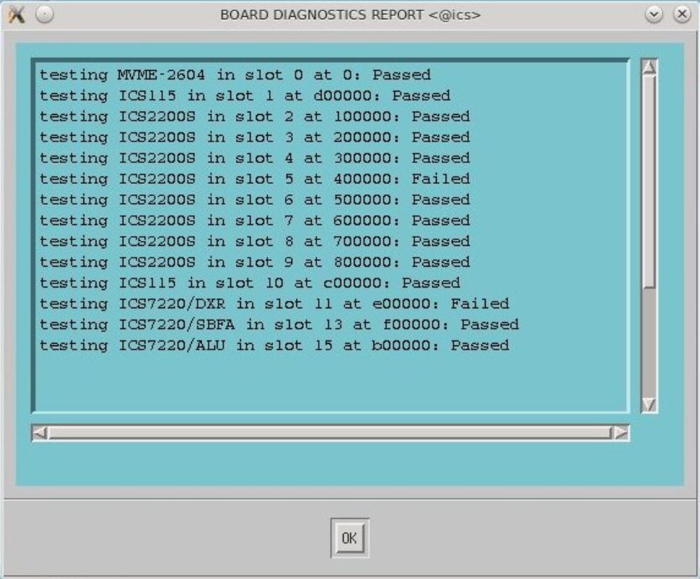
The ICS2200S in slot 5 and the DxR board failed the diagnostic test. But this may be related to incorrect jumpers or cabling.
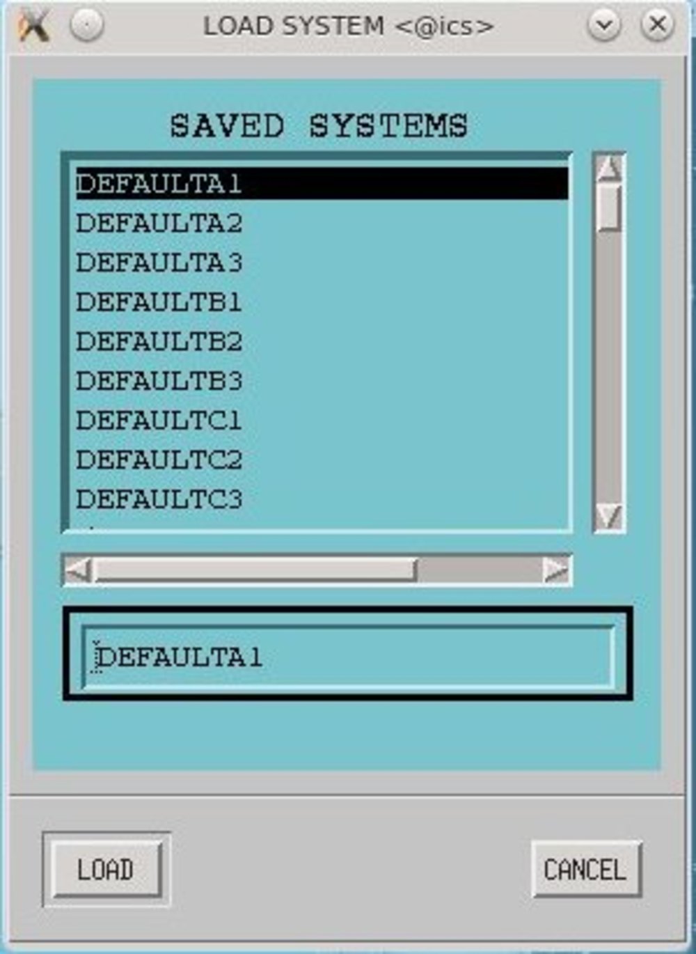
Loading a cluster
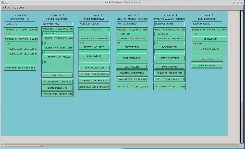
View on a cluster definition
A “Cluster” is obviously a configuration of several cards together with config data for each card.
Cross-compiling
There are several gnu versions available on the Internet, precompiled for PowerPC and for VxWorks. So this is easy. I installed an older version (gcc 2.9.6) that fits somehow to the VxWorks version 5.3.1 and compiled a hello.c:
//
#include <stdio.h>
extern int printf ( const char * format, ... );
int main(void) {
 printf("Hello, Worldn");
 return 0;
}
void testPrint(void) { printf("Hello, Worldn"); }
Note that I do not yet have a working stdio.h and can not use it so far. The packages on the net do NOT contain VxWorks libs or headers, because they are of course copyrighted.
With command line:
./ppc-gcc-296 -v -fno-builtin -I ~/ics-files/devel/C/TornadoPPC/target/h/ -nostdinc -O -c -DCPU=PPC604 hello.c
A hello.o is created. The ppc-gcc-296 is a simple shell script that extends the path to find all the ppc compiler executables:
echo "ppc-gcc wrapper..." PATH=/home/dennis/ppc/gcc/host/x86-linux/bin/:${PATH}
powerpc-wrs-vxworks-gcc "$@"
Regarding options: -nostdinc suppresses the use of host-side standard
includes/headers. I want that only target-side headers are used and make the
root to them known with -I <path>. -no-builtin prevents use of
(host-side) builtin functions. -DCPU=PPC604 is realized to my CPU model 604.
Note: No linking (no “ld …”) is required for VxWorks. It simply uses the .o files. (It is possible to use ld on the host to create a single .o-File from a set of .o-Files.)
VxWorks does not use the oncept of main-functions as entry points for the OS. To load the file on the target use:
ld <hello.o

hello.o value = 0 = 0x0
Now, all functions inside the .o file can be called simply by using their name ( we have “main” and “testPrint”):
\-> testPrint Hello, World value = 13 = 0xd ->
So that was easy. I have a working cross compile environment for the ICS-1000.
